





BLOG
Broadwall Double Ridge Waveguide Coupler Directivity Explained
July 24, 2026
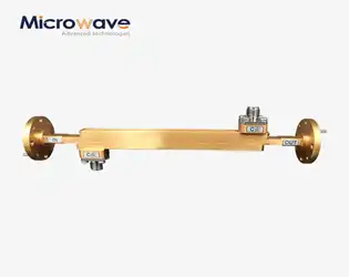
When it comes to a broadwall double-ridge waveguide coupler, directivity means that the part can tell the difference between forward and reflected signals. This makes sure that measured power only comes from the desired transmission direction. This passive microwave device collects RF signals over very large frequency ranges. It solves a problem that has been around for a long time in microwave engineering: getting multi-octave bandwidth without signal separation being compromised. The double-ridged shape capacitively loads the waveguide center, making it more operationally broad than rectangular designs while keeping high directed discrimination, which is usually more than 15-20 dB across the whole spectrum.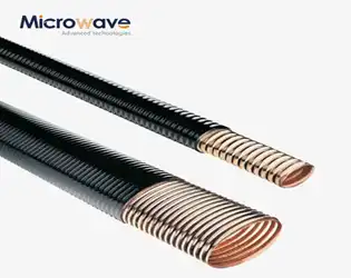
Elliptical Microwave Waveguides: Attenuation Curves Decoded
July 24, 2026
To understand elliptical microwave waveguides, you need to know more than just the basics of how RF signals work. These specialized components utilize a corrugated elliptical cross-section to guide electromagnetic energy with remarkable efficiency, combining the low-loss traits of standard fixed waveguides with unprecedented installation freedom. Attenuation curves show how signal strength decreases across frequency bands. This has a direct effect on how well systems work in telecom towers, satellite uplinks, and radar installations. We make elliptical microwave waveguides with UV-resistant polyethylene jackets and corrugated copper construction at Advanced Microwave Technologies Co., Ltd. These are designed to deliver better performance while reducing deployment complexity in mission-critical applications ranging from 3 GHz to 40 GHz.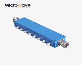
Coaxial Variable Attenuator vs Step Attenuator Tradeoffs
July 24, 2026
Which one to choose between a step attenuator and a coaxial variable attenuator depends on the needs and priorities of the application. Coaxial variable attenuators let you change the signal amplitude in a smooth, continuous way. This makes them essential for fine-tuning RF systems during testing or calibration, where precise incremental control is needed. On the other hand, step attenuators offer precise attenuation levels that are easy to repeat and work with numbers, which is important for automatic test settings and programmable systems. Both types of devices are very important in microwave engineering. However, procurement managers and RF engineers need to know about the technical tradeoffs between them in order to make sourcing decisions that meet the needs of mission-critical applications. These tradeoffs include insertion loss and frequency flatness, as well as mechanical durability and cost.
Best directional couplers for rf power monitoring systems
July 23, 2026
When you build or upgrade RF power tracking systems, the Directional Coupler is one of the most important parts that affects how accurate the measurements are and how reliable the system is. This passive device picks up signal energy moving through transmission lines without getting in the way of the main RF path. This lets engineers keep an eye on both forward and reflected power all the time. The best Directional Couplers have high directivity (often over 30dB), low insertion loss, wide frequency coverage, and strong construction, making them ideal for use in defence radar, satellite ground stations, and telecommunications infrastructure. To choose the right model, you have to balance technical details like coupling factor and power handling with buying issues like customisation support and supply chain timeliness. This affects both the performance of the system and the success of the project as a whole.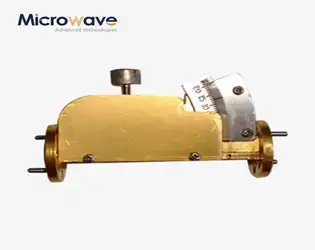
How Resistive Card Position Tunes Variable Waveguide Attenuator Depth
July 23, 2026
In variable waveguide attenuators, the resistive card position directly controls attenuation depth by modulating the interaction between the electromagnetic field and the resistive element. As the card moves deeper into the waveguide's electric field region, it absorbs more RF energy, increasing insertion loss progressively. This mechanical adjustment allows engineers to achieve precise signal power control—from minimal attenuation near the waveguide wall to maximum absorption at the field's peak—making the variable waveguide attenuator indispensable for applications demanding dynamic signal management across radar, satellite communication, and high-frequency testing environments.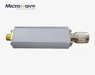
How Coaxial Detectors Measure Pulse Power in Radar Systems
July 23, 2026
By transforming high-frequency RF pulses into quantifiable DC or low-frequency output voltages, coaxial detectors form the basis for precise pulse power measurement in contemporary radar systems. These unique gadgets use point-contact diodes and carefully designed microwave matching circuits to record short-term power levels very accurately, often in the nanosecond range. Because they keep signals intact across wide frequency ranges while minimizing reflection losses, they are essential for mission-critical uses in defense radar, aerospace navigation systems, and electronic countermeasures, where even small measurement errors can threaten safety and effectiveness.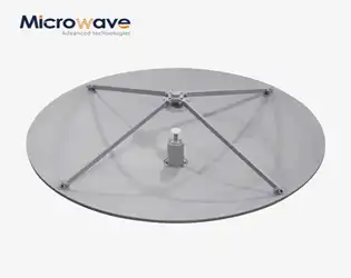
Does Subreflector Shaping Reduce Cassegrain Antennas Sidelobes?
July 22, 2026
Yes, subreflector shape does lessen sidelobes in Cassegrain antennas by making the electromagnetic wavefront distribution more uniform. Traditional hyperbolic subreflectors often make secondary radiation lobes that aren't needed. These lobes interact with channels next to them and make the system work less well. The surface of the secondary reflector can be changed to control the phase and amplitude variations across the opening using carefully planned shaping methods. This method works really well in places like satellite ground stations and radar sites that have to follow very strict sidelobe envelope rules. Modern dual-reflector antenna systems with shaped subreflectors routinely get sidelobe suppression improvements of 3–5 dB compared to older designs. This makes the signal clearer and lessens interference with nearby communication systems.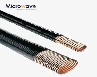
Elliptical Microwave Waveguides vs Rectangular: Loss Compared
July 22, 2026
When looking at signal loss in microwave transmission systems, elliptical microwave waveguides usually have 15–30% less insertion loss than rectangular ones at frequencies above 18 GHz. Their better performance comes from their corrugated shape, which lowers wall current density and mode conversion losses. Advanced Microwave Technologies engineers have noticed that elliptical designs have better VSWR performance—often below 1.15:1 across operational bands—while rectangular waveguides need more flange connections, which add reflection points and total loss in long-distance installations.