


BLOG
Coaxial Bandpass Filter Insertion Loss — Cavity Q Factor Limits
July 14, 2026
Understanding the relationship between insertion loss and cavity Q factor in coaxial bandpass filters is essential when selecting RF components for mission-critical systems. Insertion loss measures the signal power reduction as it passes through the filter, directly impacting link budget and system efficiency. The cavity Q factor quantifies how efficiently the resonant structure stores electromagnetic energy relative to dissipation. Higher Q values correspond to sharper frequency selectivity and lower losses, making this parameter crucial for procurement engineers sourcing bandpass filters for defense radar, satellite ground stations, or cellular infrastructure where every tenth of a dB matters.
When Low Phase Noise Amps Matter Most in Your RF Chain?
July 14, 2026
When your RF system requires exceptionally pure spectral lines, such as in radar tracking, satellite ground stations, or quantum research, where even very small jitter can hurt target resolution or quantum coherence, low phase noise amps become mission critical. These special devices reduce additive phase noise and flicker noise more than regular amplifiers that just boost gain. This keeps your carrier signal clean during frequency synthesis or local oscillator distribution. In high-order modulation methods and Doppler radar systems, this difference has a direct effect on the error vector magnitude.
Coaxial Detectors in EW Systems: SWaP-C Considerations
July 14, 2026
For signal detection and power measurement across broadband microwave frequencies in electronic warfare (EW) environments, coaxial detectors are essential components. These gadgets change high-frequency radio waves (RF) signals into outputs that can be measured. This lets system operators keep a close eye on electromagnetic activity. Procurement engineers who want to put together reliable, mission-ready EW platforms need to know how the Size, Weight, Power, and Cost (SWaP-C) parameters affect the choice of detectors.
Coaxial Load Selection Factors for High-Power Applications
July 13, 2026
Selecting the right RF termination components for high-power systems requires careful consideration of multiple technical and operational factors. Coaxial Loads serve as essential elements in radio frequency and microwave architectures, absorbing transmitted energy to protect sensitive equipment and ensure accurate testing. These passive components convert RF energy into heat, preventing reflections that could damage amplifiers or distort signals. When specifying terminations for defense radar, satellite ground stations, or broadcast transmitters, procurement engineers must evaluate power handling, thermal management, and frequency performance to ensure long-term reliability and system integrity.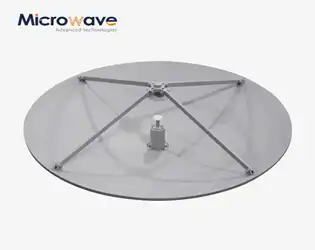
Can Cassegrain Antennas Achieve 50 dB Gain Under 1 m Dish?
July 13, 2026
Different companies use different rotating precise technologies in Cassegrain antennas, a variable waveguide attenuator. Some use worm gears to cut down on torque and make things more repeatable. Others use ball detents or friction locks to keep the place even when the machine is shaking. The attenuator's ability to consistently repeat the same reduction value when set back to a certain dial setting depends on how well these systems are made mechanically. Advanced Microwave Technologies Co., Ltd. has made rotary mechanisms that have been tried in a range of weather conditions and vibration levels that meet MIL-DTL-3933 standards. These mechanisms are reliable in aircraft and defence settings.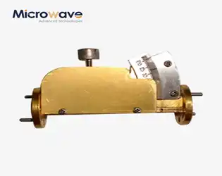
Does Rotary Precision Affect Variable Waveguide Attenuator Accuracy?
July 13, 2026
Yes, rotary precision significantly influences variable waveguide attenuator accuracy. The mechanical resolution of the rotary vane mechanism directly determines how precisely attenuation levels can be adjusted and repeated. When you work with high-frequency RF systems where signal integrity matters, even minor deviations in the rotary positioning translate to measurable errors in insertion loss. Variable waveguide attenuators rely on the precise angular movement of an absorbing element within the waveguide structure. Without adequate rotary precision, the device cannot maintain consistent attenuation settings, compromising calibration stability and measurement reliability critical for radar testing, satellite ground stations, and defense applications.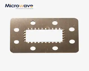
Does Compression Rate Affect EMI Waveguide Gaskets Shielding?
July 10, 2026
The compression rate does have a direct and important effect on how well EMI waveguide gaskets protect. When these special gaskets are pressed down properly, they make close metal-to-metal contact between the sides of two flanges that fit together. This lowers the contact resistance and stops electromagnetic interference from leaking out at important waveguide joints. If you don't compress the gasket enough, tiny air holes form that let leaks happen. If you compress it too much, conductive particles inside the matrix can become forever deformed, which hurts both its mechanical integrity and its ability to conduct electricity. To get the best shielding across microwave and RF bands in mission-critical systems, you need to understand and control the compression settings.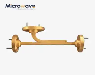
Broadwall Coupler vs Crossguide — Which Handles Higher Power?
July 10, 2026
When evaluating high-power microwave components, the broadwall coupler consistently outperforms crossguide alternatives in power handling capacity. This benefit comes from the fact that it is strong, made of a high-grade aluminum alloy or silver-plated copper, and has many openings spread out across the wide wall of the waveguide. These couplers can usually handle high power levels of kilowatts to megawatts. The only thing that limits them is the waveguide breakdown voltage, not their structural stability. Broadwall couplers are the best choice for radar emitters, satellite uplink systems, and particle accelerators, where power density and stability can't be compromised because they are air-dielectric and better at dissipating heat.