


BLOG
How Coaxial Detectors Measure Pulse Power in Radar Systems
July 23, 2026
By transforming high-frequency RF pulses into quantifiable DC or low-frequency output voltages, coaxial detectors form the basis for precise pulse power measurement in contemporary radar systems. These unique gadgets use point-contact diodes and carefully designed microwave matching circuits to record short-term power levels very accurately, often in the nanosecond range. Because they keep signals intact across wide frequency ranges while minimizing reflection losses, they are essential for mission-critical uses in defense radar, aerospace navigation systems, and electronic countermeasures, where even small measurement errors can threaten safety and effectiveness.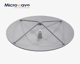
Does Subreflector Shaping Reduce Cassegrain Antennas Sidelobes?
July 22, 2026
Yes, subreflector shape does lessen sidelobes in Cassegrain antennas by making the electromagnetic wavefront distribution more uniform. Traditional hyperbolic subreflectors often make secondary radiation lobes that aren't needed. These lobes interact with channels next to them and make the system work less well. The surface of the secondary reflector can be changed to control the phase and amplitude variations across the opening using carefully planned shaping methods. This method works really well in places like satellite ground stations and radar sites that have to follow very strict sidelobe envelope rules. Modern dual-reflector antenna systems with shaped subreflectors routinely get sidelobe suppression improvements of 3–5 dB compared to older designs. This makes the signal clearer and lessens interference with nearby communication systems.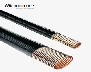
Elliptical Microwave Waveguides vs Rectangular: Loss Compared
July 22, 2026
When looking at signal loss in microwave transmission systems, elliptical microwave waveguides usually have 15–30% less insertion loss than rectangular ones at frequencies above 18 GHz. Their better performance comes from their corrugated shape, which lowers wall current density and mode conversion losses. Advanced Microwave Technologies engineers have noticed that elliptical designs have better VSWR performance—often below 1.15:1 across operational bands—while rectangular waveguides need more flange connections, which add reflection points and total loss in long-distance installations.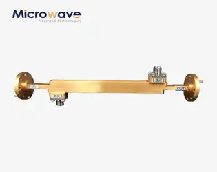
Why Broadwall Double Ridge Waveguide Couplers Handle High Power
July 22, 2026
Broadwall double ridge waveguide couplers are great at handling high power because they have a special shape that combines bigger dimensions with carefully placed internal ridges that spread electromagnetic energy more evenly across the waveguide cross-section. This arrangement lowers the amount of current concentrated at any one point. This lowers the risks of resistive heating and voltage breakdown, even when continuous wave signals at the kilowatt level pass through the structure. The broadwall orientation places the coupling apertures on the waveguide's wider face, which allows for more space between the holes and better thermal dissipation paths than the narrowwall variants. This makes these parts essential for radar transmitters, electronic warfare systems, and high-power test equipment that needs to be reliable in harsh conditions.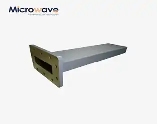
Overheating and Arcing — Termination Waveguide Failure Modes
July 21, 2026
In high-power microwave and RF systems, the termination waveguide serves as a critical safety component designed to absorb excess electromagnetic energy and convert it into heat, preventing destructive signal reflections. When these devices experience overheating or arcing, the consequences extend beyond component failure—entire radar systems, satellite ground stations, and communication networks face catastrophic damage. Overheating occurs when thermal dissipation exceeds design capacity, while arcing results from voltage breakdown within the absorbing medium. Both failure modes compromise system integrity, damage expensive amplifiers, and halt mission-critical operations. Understanding these phenomena enables procurement engineers and technical teams to select robust components that ensure long-term reliability.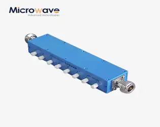
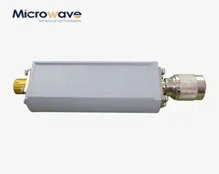
What Freq Range Should a Coaxial Variable Attenuator Cover?
July 21, 2026
In mission-critical RF and microwave uses, picking the right frequency range for a coaxial variable attenuator has a direct effect on how well the system works. For lower-frequency uses, coaxial variable attenuators usually cover ranges from DC to 1 GHz. For mid-band communications, they cover ranges from 1 GHz to 6 GHz. Above 6 GHz, they often go up to 18 GHz or 40 GHz for aerospace, defense, and satellite systems. The best frequency coverage depends on the needs of your application, such as the amount of bandwidth needed, the level of signal integrity that can be tolerated, and how well it can be integrated with existing transmission infrastructure. Making sure that the frequency range fits your needs perfectly is the best way to get the best insertion loss, VSWR performance, and measurement accuracy.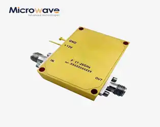
Low Phase Noise Amps: Flicker Corner and Its Impact on SNR
July 21, 2026
Low phase noise amps are special RF parts that are made to keep the signal's spectral clarity while it's being amplified. In contrast to regular amplifiers that only care about gain or noise figure, these devices reduce the amount of added phase shift close to the carrier frequency. Signal-to-noise ratio (SNR) performance in mission-critical applications is directly controlled by the flicker corner frequency, which is where 1/f noise meets thermal noise. When procurement teams understand this relationship, they can choose amplifiers that keep signals intact in harsh environments like those found in satellite communications, radar systems, and precision measuring equipment.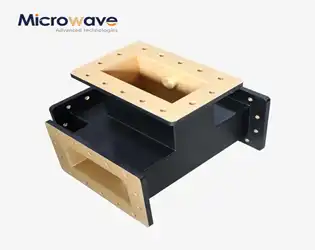
H Plane Tee in Microwave — Shunt Junction Impedance Characteristics
July 20, 2026
As a shunt junction, the H plane tee in microwave systems splits or joins electromagnetic power with matched phase relationships. This three-port waveguide works in the magnetic field plane and has parallel resistance properties that let signals travel in phase between ports that are close to each other. It is very important for radar beamforming networks, satellite feeds, and test measurement assemblies to accurately characterize shunt junction impedance because it directly affects reflection coefficients and power transfer efficiency. Engineers can predict VSWR performance and make matched networks work better for mission-critical RF designs by understanding how these impedances behave.