





BLOG
Miter Bend Waveguide Guide: Structure, Materials, and Industrial Uses
April 15, 2026
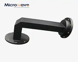
A big problem in engineering high-frequency microwave systems is getting electromagnetic signals to go around corners without losing any of their strength. The miter bend waveguide is a well-thought-out solution that uses a unique 45-degree reflective plane at sharp corners to efficiently reroute microwave energy. Instead of sweeping bends, Miter Bend Waveguide, which takes up a lot of room, these small waveguide parts work with limited space in places like defense radar, satellite payloads, and telecommunications infrastructure, where every centimeter counts. Our detailed guide breaks down the structural engineering, material science, and industrial use of these important RF components. It gives procurement engineers and technical decision-makers useful information for finding and integrating these parts.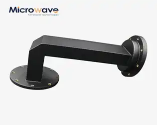
Miter Bend Waveguide in Microwave Systems: Features and Selection Tips
April 15, 2026
Engineers and procurement professionals often have to figure out how to send electromagnetic energy around tight corners without losing the integrity of the signal when they are working with Miter Bend Waveguide microwave systems that send high-frequency signals. This is exactly where waveguide parts that were carefully designed and built come in handy. The Miter Bend Waveguide stands out as a space-saving option that can redirect microwave signals at sharp angles, usually 90 degrees, while still having low insertion loss and great return loss. Traditional sweeping bends take up a lot of space. These small parts, on the other hand, use a precisely machined reflective plane set at a 45-degree angle to efficiently guide electromagnetic waves through changes in direction. Knowing the special qualities and choosing rules for these important RF parts can have a huge effect on how well a system works, especially in situations where space is limited and signal quality, reliability, and accuracy are all musts.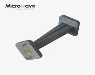
Precision Waveguide Twists For K-, Ka-, V- and W-Bands
April 15, 2026
Precision Waveguide Twist components are important passive microwave devices designed to make it possible for high-frequency transmission systems to control the rotation of electromagnetic waves' polarization. These parts are very important for K-band (18–27 GHz), Ka-band (26.5–40 GHz), V-band (40–75 GHz), and W-band (75–110 GHz) uses, where it's important to keep the signal's integrity while allowing for changes in physical orientation. We make these devices at Advanced Microwave Technologies Co., Ltd. (ADM) using five-axis CNC precision machining. This lets us rotate the polarization 90° or 180° while keeping the insertion loss below 0.1dB. Our range of products covers frequencies from 2.2GHz to 110GHz and continuous wave power from 1kW to 50kW. These products are reliable for high-power industrial microwave applications, phased array radar systems, and satellite communication payloads.
Where to Buy Reliable AC Power Amplifiers for Your Projects
April 14, 2026
Sourcing a reliable AC power amplifier for precision testing demands careful evaluation of supplier capabilities, technical specifications, and global logistics networks. Whether you're an aerospace OEM testing avionics power systems or a research lab simulating grid disturbances, partnering with manufacturers who demonstrate proven expertise in high-frequency signal integrity, custom engineering, and compliance with international standards like ISO 9001 ensures your projects meet stringent performance benchmarks without costly delays or quality compromises.
Design Guidelines for High-Performance RF Rotary Joints in Aerospace Applications
April 14, 2026
Designing high-performance RF rotary joints for aerospace applications demands meticulous attention to electromagnetic coupling principles and mechanical precision. The RF rotary joint working principle centers on maintaining continuous signal transmission between stationary and rotating structures through impedance-matched interfaces, typically achieving Z₀ = 50Ω across the rotating boundary. Aerospace-grade designs must balance ultra-low insertion loss (<0.5 dB), minimal VSWR (<1.3:1), and exceptional phase stability under extreme temperature fluctuations, vibration profiles, and rotational speeds exceeding 300 RPM—all while ensuring mission-critical reliability over millions of rotation cycles.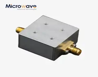
Difference Between Coplanar Waveguide, Microstrip, Stripline, & Other Planar Transmission Lines
April 14, 2026
When designing microwave circuits and RF systems, engineers face critical choices between planar transmission line technologies. Coplanar waveguide (CPW) features signal and ground planes on the same substrate surface, offering superior ease of integration with surface-mount components. Microstrip places the signal trace atop a grounded dielectric substrate, delivering compact dimensions. Stripline sandwiches the conductor between two ground planes, providing excellent electromagnetic shielding. Each transmission line architecture brings distinct electromagnetic properties, fabrication requirements, and performance trade-offs that directly impact signal integrity, power handling, and system reliability in mission-critical applications.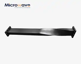
Design of integrated waveguide twist components
April 13, 2026
To get the best performance out of a Waveguide Twist, you need to carefully choose the parts, install them correctly, and keep an eye on the system all the time. For devices like the Waveguide Twist, which works at frequencies between 10.7 GHz and 12.75 GHz, it's important to keep insertion loss as low as possible (ideally ≤0.5 dB), port-to-port isolation as high as possible (≥70 dB), and impedance matching across the whole operating bandwidth. Controlling the temperature is also very important, especially for systems that handle up to 200W of power, since changes in temperature from -40°C to +85°C can change the way filters work. Regular checks with vector network analyzers and following strict installation procedures greatly increase the life of Waveguide Twist while keeping the integrity of signals in radar and satellite communication applications.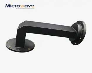
Choosing the Right Miter Bend Waveguide for High-Frequency Systems
April 13, 2026
Choosing the right waveguide bend component is very important when designing high-frequency RF and microwave systems. It can make or break the integrity of the signal. A Miter Bend Waveguide is a space-saving solution that guides electromagnetic waves around sharp angles by using internally reflective surfaces that are precisely machined. Unlike traditional curved bends that need a lot of installation space, Miter Bend Waveguide designs take up 30 to 50 percent less space while still being very good at transmitting power. This part is very useful in places where performance and size are important, like satellite communications, radar systems, and telecommunications infrastructure. When procurement teams and system designers understand the details of Miter Bend Waveguide technology, they can make choices that are in line with mission-critical operational needs.