




How Coupling Coefficients Tune Coaxial Bandpass Filter Response
When selecting RF components for mission-critical applications, understanding how coupling coefficients control filter behavior becomes paramount. Coaxial bandpass filters rely on electromagnetic interactions between internal resonators, quantified as coupling coefficients, to define their frequency response characteristics. These coefficients directly determine passband width, insertion loss profiles, and stopband rejection performance. By adjusting physical spacing, capacitive loading, or inductive coupling structures within the coaxial housing, engineers manipulate these coefficients to achieve desired filter responses—from ultra-narrow channel selection in satellite ground stations to broader passbands in telecom base stations. This fundamental relationship between coupling strength and filter performance enables precise customization, making coaxial designs indispensable for aerospace radar systems, defense communications, and wireless infrastructure demanding both reliability and tailored spectral control.
Understanding Coaxial Bandpass Filters and Their Role in RF Systems
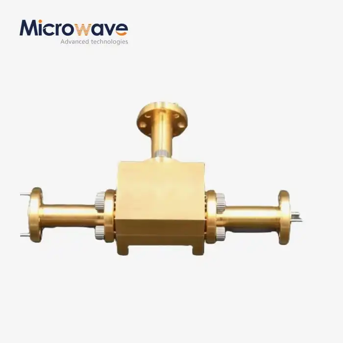
In complex RF systems, coaxial bandpass filters enable only specific signal bands to pass through with minimum loss while limiting interference from other bands. Their structure uses cylinder-shaped metal housings with regulated resonant chambers produced by inner wires and exterior shields for transverse electromagnetic mode transmission. Excellent electromagnetic shielding reduces outside interference with this design. This advantage is crucial in congested spectrum environments like cellphone base stations and airport security radars.
Coaxial Bandpass Filters can withstand more continuous-wave power than ceramic resonators. They can frequently take over 100 watts without overheating. Small-area surface acoustic wave filters can only handle a limited frequency and power range. Cavity filters perform effectively but take up space. When compactness, power management, and harsh environment endurance are needed, the Coaxial Bandpass Filter design is ideal for 500 MHz to 18 GHz applications.
Why Coaxial Filters Dominate High-Reliability Applications
Defense contractors and aerospace system integrators choose Coaxial Bandpass Filters because they can handle shocks, vibrations, and temperature changes from -55°C to +85°C. The all-metal construction naturally provides better passive intermodulation performance than dielectric-loaded alternatives. This is important for keeping signals from getting distorted in multi-carrier transmitter combiners that are used on military aircraft and ships.
The Critical Role of Coupling Coefficients
Coupling coefficients measure energy transmission between two resonators. These numerous parameters, generally between 0.01 and 0.15, regulate how rapidly a filter shifts from passband to stopband. When reviewing datasheets, procurement engineers should realise that tighter coupling (higher coefficient values) widens bandwidths but may induce passband ripple. Conversely, weaker coupling reduces selectivity but increases manufacturing tolerance sensitivity. Your spec discussions with ADM are better when you understand this trade space. While developing microwave components for ADM, our technical team has improved coupling control for 20 years.
New design approaches allow you to manage inter-resonator coupling and external coupling (input/output matching) independently, giving you additional possibilities. This function is helpful for constructing filters for radio feed networks or adding pieces to space-limited transceiver modules with electrical and physical size restrictions.
How Coupling Coefficients Tune Coaxial Bandpass Filter Response — Principles and Mechanisms
Mixed-mode coupling, capacitive electric field coupling, and inductive magnetic field coupling occur between resonators. Large holes in the shared walls govern inductive coupling, whereas the gap separation between the resonator posts controls capacitive coupling. Changing these physical measures during manufacture directly affects the coupling coefficient values and the coaxial bandpass filter response.
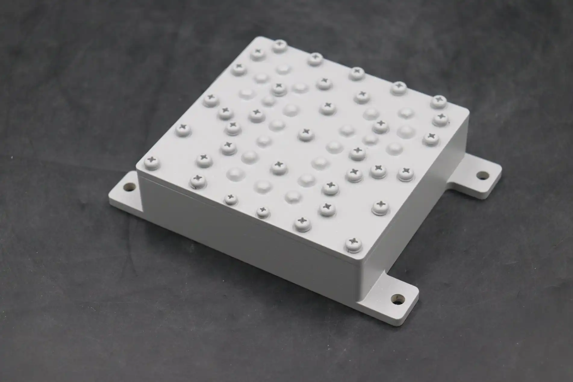
The coupling coefficient changes the bandwidth most noticeably. A combline filter with a 10 MHz passband centred at 2.4 GHz may employ coupling factors close to 0.03. Assuming proportionate step adjustments, doubling these factors to 0.06 increases bandwidth to 20 MHz. Because parasitic connections and fringing field effects make things less linear as spacing gets smaller, electromagnetic simulations must confirm this linear relationship to simplify initial design.
Mechanical Tuning Methods for Production Control
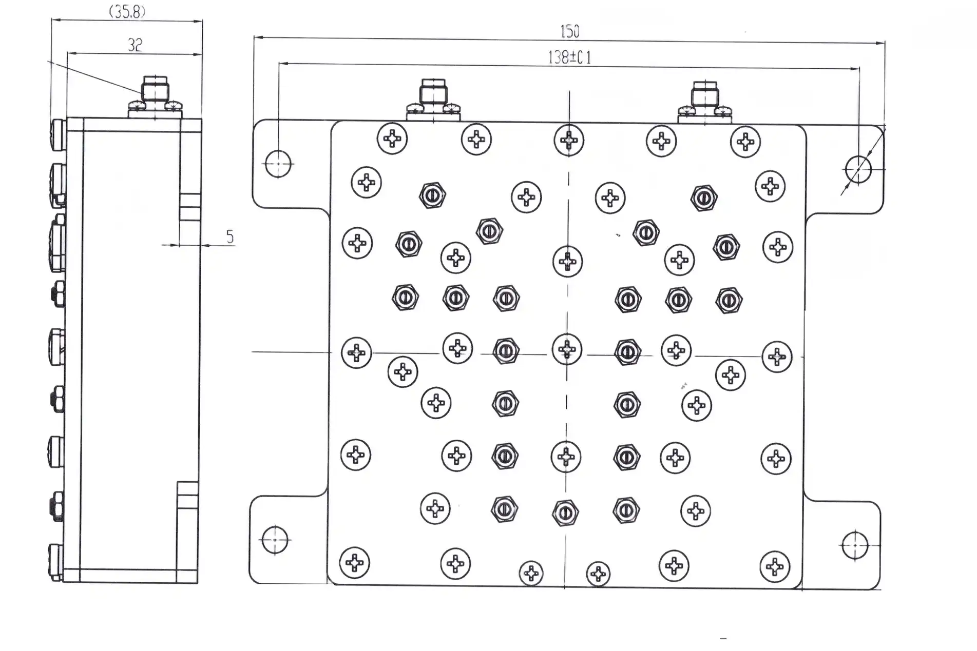
Precision machining is used by manufacturers to set the starting dimensions of the couplings, and important gaps can be within ±0.025 mm of the true dimensions. For post-assembly tuning, screws that can be adjusted are inserted into resonator holes. The depth of the screws changes the local capacitance, which in turn changes the coupling strength. ADM's ISO 9001:2015-certified production facility has tuning stations that are guided by vector network analyzers. This is where technicians change couplings over and over again while keeping an eye on S-parameters in real time. This time-consuming process makes sure that each filter meets certain standards for speed and return loss before it is shipped.
Trade-Offs Between Selectivity and Insertion Loss
Increasing coupling factors to make the bandwidth bigger naturally lowers the contribution of the empty Q-factor to the total insertion loss. A four-resonator filter with a coupling of 0.02 might have an insertion loss of 0.8 dB. Increasing the coupling to 0.05 for a wider response could make the loss 1.2 dB. When comparing different suppliers, buying teams should ask for detailed loss budgets that show how coupling affects the total loss. This is especially important for receiver front-end applications where every tenth of a decibel changes the system noise figure.
Environmental Stability Considerations
When the temperature changes, the dimensions of the resonators change, which changes the dielectric properties and coupling factors, which in turn changes the middle frequency. These drifts are kept to a minimum by using high-grade aluminum housings and resonator materials with the same coefficient of thermal expansion. In military standards, frequency stability must be maintained within ±0.5 MHz from -40°C to +70°C. This can only be done by carefully choosing the materials and designing the connection in a way that accounts for the expected effects of temperature. ADM's MIL-STD-810-compliant thermal cycling test protocols make sure that couplings are stable at all operational temperatures before they are sent out.
Comparative Analysis: Coaxial Bandpass Filters vs Other Filter Types in Relation to Coupling and Performance
Figuring out the relative benefits helps buyers make choices that lead to the best solutions. Coaxial Bandpass Filters are a good balance between performance and cost compared to other technologies, each with its own binding properties and use cases.
When full-height resonators are used in cavity filters, the empty Q-factors are higher than 10,000, which means that the insertion loss is less than 0.3 dB for narrow bandwidths. But their size makes them impractical below 1 GHz and in small installations like cell phone towers on rooftops. When you want to make changes to a coupling, you have to get to the big tuning elements, which makes field maintenance harder than with coaxial tuning screws.
Ceramics with a low thermal coefficient make dielectric resonator filters very stable at high temperatures, but they are much more expensive than coaxial bandpass filters of the same type. Their connection systems have ceramic post spacing and metallization patterns, which means that they can't be changed much after production. Coaxial Bandpass Filter designs work better for system integrators who need to be able to change the frequency during the prototype process.
Ceramic Filters: Compact but Constrained
Ceramic monolithic filters work well for consumer applications that need to be small, but their fixed couplings make them impossible to customize. Power handling rarely goes above 10 watts, and passive intermodulation loses its effectiveness faster than Coaxial Bandpass Filter metal-to-metal contacts. Ceramic choices are often ruled out of aerospace qualification tests because they are easily damaged by thermal shock.
SAW and BAW Technologies: Frequency Limitations
Surface acoustic wave and bulk acoustic wave filters work best below 3 GHz for cellphones, but they can't handle microwave frequencies, which is where Coaxial Bandpass Filter designs really shine. Their piezoelectric surfaces make them sensitive to temperature, so they need compensation circuits. Coaxial Bandpass Filters, on the other hand, are passively stable. In SAW devices, coupling depends on the shape of the transducer and can't be changed mechanically, but coaxial resonators can be.
Waveguide Filters: High-Power Supremacy
Radar emitters and satellite transmission chains use hollow waveguide filters because they can accommodate kilowatts without loss. Coupling using large iris apertures or posts within waveguide sections allows high-Q performance. Big and hefty, they can only be utilised in permanent places or on large platforms. Mobile and flying systems that can't employ waveguide solutions due to cost or space limits use coaxial bandpass filters, even with power loss.
When calculating the long-term total cost of ownership, buying managers should compare Coaxial Bandpass Filters' initial price to their tuning flexibility. Iris cutting on bespoke waveguide filters requires pricey gear. However, tuning screws reduce one-time engineering expenses for Coaxial Bandpass Filter designs. ADM has manufactured both technologies, so we can recommend the optimal designs depending on application needs, power costs, and integration timelines.
Best Practices for Procuring and Implementing Coaxial Bandpass Filters Tuned by Coupling Coefficients
Detailed specification documentation is the first step to successful component sourcing. Not only should procurement engineers list the center frequency and bandwidth, but they should also list the external quality needs, ripple tolerance, and group delay variation. Engineering transparency is shown by suppliers who include coupling coefficient visibility in datasheets. For example, our ADM specification sheets include measured coupling matrices for multi-resonator designs upon request, which allow for accurate system-level simulations.
Assessing a supplier's skills goes beyond just looking at their collection of products. Check to see if the makers have their own electromagnetic simulation tools, such as HFSS or CST Microwave Studio, which are needed to estimate how coupling will work in custom shapes. Ask for sample tuning reports that show as-built S-parameters aligned with specs. This will show you the real coupling precision that was achieved during production. Suppliers who can't provide this kind of paperwork may not have strict process control.
Interpreting Datasheet Parameters Related to Coupling
The passband wave shows that the coupling is the same across all steps of the resonator. Tighter specifications (less than ±0.3 dB ripple) mean that the connection is very well controlled, while ±1.0 dB limits may mean that the manufacturing standards are not as strict. Coupled magnitude errors are related to group delay ripple. For digital communications, filters should guarantee group delay flatness within ±2 nanoseconds to avoid intersymbol interference.
Customization Capabilities and Lead Time Implications
Standard catalog filters work with most frequency plans, but they don't usually improve coupling for unique uses. Custom designs let you change the coupling distribution to get different reactions. For example, a steeper lower stopband rejection can protect receivers from high-power emitters. Custom coupling designs usually add two weeks to ADM's standard eight-week production cycle, as long as clear specifications are sent with the first inquiry. Iterative coupling optimization is possible with prototyping services before committing to production tooling.
Communication with Technical Support Teams
For collaboration to work, system-level information must be shared beyond filter specs. Describe the nearby parts, the kinds of disturbance that you expect to see, and the actual limitations of the integration. Our engineering team has fixed many performance problems related to coupling by learning about installation settings, like how metal enclosures can change external coupling or how wire routing can cause unexpected resonances. Providing mechanical models and electrical plans speeds up the process of making a custom Coaxial Bandpass Filter that works perfectly.
Integration and Field Monitoring Considerations
System integrators should plan to use portable network analyzers for verification after the installation is complete. In-situ readings may show changes in the coupling caused by mechanical stress during installation or temperature cycling after shipping. Field changes with accessible tuning screws let you get back to the normal reaction without having to replace any parts. Take pictures and record the S-parameters of the initially tuned settings to keep track of them and use them as a starting point for future maintenance. ADM includes detailed tuning instructions with every shipment, which connect screw positions to changes in the coupling coefficient based on a description made before delivery.
Case Studies: Real-World Examples Demonstrating the Effect of Coupling Coefficients on Coaxial Bandpass Filter Performance
A local phone carrier requested that ADM to enhance neighbouring channel rejection for 2.4 GHz point-to-multipoint base stations with Wi-Fi issues. Their original four-resonator filters had a 40 dB rejection at ±15 MHz shifts, making them unsuitable for urban areas. The solution was coupling coefficient redistribution. Weaker first- and last-stage couplings and stronger interior couplings sharpened the skirt response without affecting the number of resonators or bandwidth. Electromagnetic simulation showed 52 dB rejection from this coupling optimisation. The coupling-tuned strategy worked since prototype units rejected 51 dB. The telecom firm reported a 30% decline in interference-related service calls following the installation. This illustrates that accurate coupling control affects operations. Product performance was consistent within ±1.5 dB specification windows for 500 units.
A military aerospace program needs tiny filters for aerial surveillance radar at 10 GHz. Size restricted the number of resonators to three, making bandwidth and rejection requirements difficult to accomplish. The requisite 150 MHz bandwidth was attained with coupling coefficients close to 0.08. The initial samples contained 2.1 dB insertion loss, which exceeded receiver sensitivity limits. In a collaborative design iteration, aluminium resonators were replaced with silver-plated copper. This increased unloaded Q from 800 to 1200. When the coupling iris shape was adjusted to reduce fringing losses, insertion loss was reduced to 1.4 dB, but bandwidth remained the same. Military business tested filters using MIL-STD-810 vibration and heat cycles. The central frequency varied by less than 3 MHz, while coupling stability maintained a bandwidth of ±5 MHz from -40°C to +85°C.
A satellite ground station manufacturer wanted Ka-band uplink filters that could take 50 watts continuously. Standard coupling systems were at risk when voltage fell at tiny resonator gaps required for tight coupling. ADM combined loose direct coupling with cross-coupling between resonators far apart. Electrical responsiveness was maintained while gap widths were safe. No arcing or passive intermodulation development occurred after 30 minutes of 75-watt testing, proving the design's strength. Later, the integrator coupled ground stations in this manner throughout their worldwide network.
Conclusion
Coupling coefficients are the main way that coaxial bandpass filters are tuned to give accurate frequency response characteristics that current RF systems need. These factors directly affect bandwidth, selectivity, and insertion loss by controlling the electromagnetic interaction between resonators. Mechanical changes allow for both tuning in production and optimizing in the field. Coaxial Bandpass Filter architecture is better at balancing performance, size, and cost than cavity, ceramic, or SAW alternatives for uses between 500 MHz and 18 GHz, especially when handling power and being durable in harsh environments are important. To make a good purchase, you need to check how good the seller is at controlling couplings, figure out what the factors on the datasheet mean for coupling accuracy, and keep the lines of communication open during the custom design process. Experiments in the real world show that careful coupling optimization makes a system better at blocking interference, making signals clear, and keeping it running reliably.
FAQ
What specific impact do coupling coefficients have on insertion loss?
There are several ways that coupling factors affect insertion loss. Greater coefficient values mean that there is more electromagnetic field buildup at resonator gaps. This makes resistive losses in metal surfaces greater and adds to the dissipation. On the other hand, weaker coupling lowers these gap losses, but it may take more resonator stages to get the same level of selectivity, which increases the total loss. The best way to connect things is to balance the amount of bandwidth needed with the amount of loss that can be tolerated. For well-designed filters, this usually means keeping the insertion loss below 1.5 dB for most commercial uses.
Can coupling coefficients be adjusted after manufacturing?
Yes, the majority of Coaxial Bandpass Filters have tuning screws that allow for post-manufacturing coupling changes in the resonator holes. The depth of the screw entry changes the local capacitance, which changes how strongly two neighboring resonators are coupled. This adjustability lets you make up for manufacturing flaws and find the best settings for each installation site. To meet strict requirements, suppliers like ADM regularly use this feature for production tuning. System programmers, on the other hand, can use portable network analyzers and written tuning processes to make small changes in the field.
How do I choose between coaxial and other filter types based on coupling needs?
The choice is based on the frequency range, the amount of power it can handle, its size, and its ability to be tuned. Coaxial Bandpass Filters are good for uses that need to be able to change the coupling field, handle 10 to 200 watts of power, and work with frequencies between 500 MHz and 18 GHz. If you need to keep the insertion loss below 0.5 dB despite the larger size, choose cavity filters. For fixed-frequency market electronics under 10 watts that need to be cheap, choose ceramic filters. Choose waveguide filters based on the maximum power level in kilowatts and their best performance, even if it means they are bigger or heavier.
Partner with ADM for Precision Coaxial Bandpass Filter Solutions
Advanced Microwave Technologies Co., Ltd has been developing and making high-performance Coaxial Bandpass Filters with carefully controlled coupling coefficients for more than 20 years. Our ISO 9001:2015-certified facility has cutting-edge vector network analysis tools that can work up to 110 GHz. These tools allow for precise coupling measurement and tuning for high-stakes aerospace, military, and telecommunications applications. During the design, testing, and production phases, our engineering team provides expert technical support for all of your needs, whether your project needs standard catalog filters or fully customized coupling distributions for asymmetric response shaping.
As a reliable provider of coaxial bandpass filters for mission-critical RF systems around the world, we follow strict quality control procedures that include testing for passive intermodulation below -150 dBc and environmental qualification to MIL-STD-810 standards. Rapid development speeds up the process of making changes to a design, and flexible manufacturing can handle both small-batch R&D orders and high-volume production runs with the same level of accuracy. Email our team at craig@admicrowave.com to talk about your specific filter needs, get detailed documentation on coupling coefficients, or set up a technical consultation. ADM has a lot of experience with coupling control, which can help you make your next RF system design better.
References
1. Matthaei, G.L., Young, L., and Jones, E.M.T. Microwave Filters, Impedance-Matching Networks, and Coupling Structures.
2. Cameron, R.J., Kudsia, C.M., and Mansour, R.R. Microwave Filters for Communication Systems: Fundamentals, Design, and Applications.
3. Hong, J.S. and Lancaster, M.J. Microstrip Filters for RF/Microwave Applications.
4. Rhodes, J.D. Theory of Electrical Filters.
5. Hunter, I.C. Theory and Design of Microwave Filters.
6. Levy, R. "Filters for Communications Satellites."