


What are the Main Types of Waveguide Power Dividers and Their Differences?
Waveguide power dividers are essential components in high-frequency microwave systems, designed to efficiently split electromagnetic signals into multiple paths with minimal loss. As modern communication systems, radar technologies, and aerospace applications continue to advance, understanding the various types of waveguide power dividers and their distinctive characteristics becomes increasingly important for engineers and system designers. This comprehensive guide explores the main types of Waveguide Power Dividers available in today's market, comparing their unique features, applications, and performance characteristics to help you select the optimal solution for your specific requirements.
T-Junction, Y-Junction, and E-Plane/H-Plane Waveguide Power Dividers
Waveguide power dividers come in several fundamental designs, each with unique characteristics that make them suitable for specific applications. Understanding these different configurations is essential for selecting the right component for your microwave system needs.
T-Junction Waveguide Power Dividers
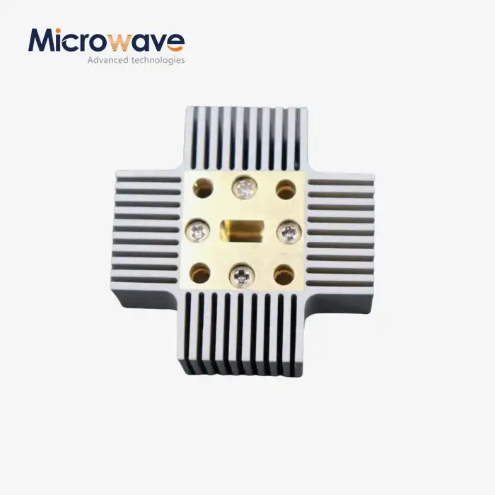
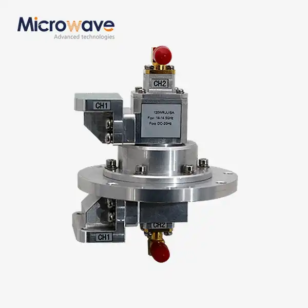
T-Junction Waveguide Power Dividers represent one of the most fundamental and widely used power division configurations in microwave engineering. These dividers feature a main waveguide channel that branches perpendicularly to form a T-shape, hence the name. The incoming signal enters through the main port and splits into two output ports at the junction. What makes T-Junction Waveguide Power Dividers particularly valuable is their relatively simple structure that can be manufactured with high precision using modern CNC machining techniques. Advanced Microwave Technologies Co., Ltd. offers T-Junction dividers in various waveguide sizes including WR-90 for X-band applications (8.2-12.4 GHz) and smaller sizes like WR-28 for higher frequency applications up to 40 GHz. These dividers typically achieve insertion losses under 0.5 dB and isolation greater than 20 dB between output ports, ensuring minimal signal degradation. T-Junction dividers are particularly well-suited for systems where power division ratio is not required to be equal, as they can be designed to provide unequal power division by adjusting the geometry of the junction. The aluminum and brass construction ensures both light weight and durability, making them ideal for aerospace applications where both performance and weight considerations are critical. These dividers can handle power levels up to 100W, making them suitable for both receiving and transmitting applications across satellite communications and radar systems.
Y-Junction Waveguide Power Dividers
Y-Junction Waveguide Power Dividers offer a different approach to power division compared to their T-Junction counterparts. As the name suggests, these dividers feature a Y-shaped structure where the input waveguide gradually bifurcates into two output waveguides at a specific angle. This gradual transition is a key advantage of Y-Junction Waveguide Power Dividers, as it typically results in better impedance matching and consequently lower VSWR (Voltage Standing Wave Ratio), generally maintaining values below 1.5 across the operational bandwidth. Advanced Microwave Technologies' Y-Junction dividers are engineered to provide exceptionally balanced power division, with amplitude imbalance typically less than 0.2 dB between output ports. The smooth transition of the Y-junction design minimizes reflections and standing waves, resulting in improved overall system performance. These dividers are available in standard waveguide sizes ranging from WR-90 down to WR-22, covering frequencies from 8 GHz to 50 GHz. The Y-junction configuration is particularly advantageous in applications requiring equal power division with minimal phase difference between output signals, such as in antenna feed networks for communications satellites. The construction materials can be customized based on application requirements, with options including aluminum for weight-sensitive applications, brass for better conductivity, or copper for maximum electrical performance. The operating temperature range of -40°C to +85°C ensures reliable performance in various environmental conditions, making Y-Junction Waveguide Power Dividers suitable for both ground-based and airborne applications.
E-Plane and H-Plane Waveguide Power Dividers
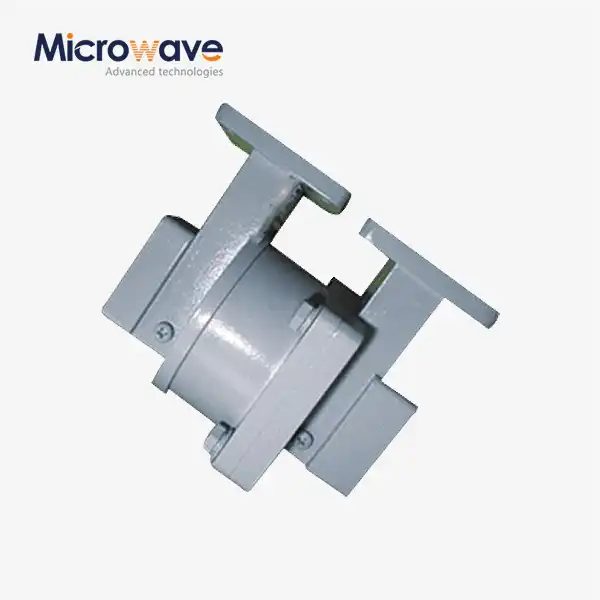
E-Plane and H-Plane Waveguide Power Dividers are categorized based on the plane in which the division occurs relative to the electric (E) and magnetic (H) field components of the propagating electromagnetic wave. E-Plane dividers split the signal in the plane parallel to the electric field, while H-Plane dividers divide the signal in the plane parallel to the magnetic field. This fundamental difference results in distinct performance characteristics that make each type suitable for different applications. Advanced Microwave Technologies' E-Plane Waveguide Power Dividers typically offer superior isolation between output ports (often exceeding 25 dB) and are preferred in applications where minimal cross-talk between channels is critical. In contrast, H-Plane Waveguide Power Dividers generally provide lower insertion loss and wider bandwidth operation, making them ideal for broadband applications. Both variants are available in standard waveguide sizes from WR-90 to WR-22, covering frequencies from 8 GHz up to 50 GHz, with custom sizes available for specialized applications. The choice between E-Plane and H-Plane configurations often depends on specific system requirements regarding isolation, bandwidth, and physical integration constraints. For example, satellite communication systems might benefit from E-Plane dividers due to their superior isolation characteristics, while radar systems might prefer H-Plane dividers for their lower insertion loss and broader bandwidth capabilities. Advanced Microwave Technologies manufactures both types with precision-machined components and carefully designed internal features to ensure optimal electromagnetic performance across the specified frequency range, with typical VSWR values maintained below 1.5 and insertion loss less than 0.5 dB across the operational bandwidth.

Multi-Way, Hybrid, and Custom Waveguide Power Dividers
Beyond the basic configurations, more complex waveguide power divider designs serve specialized applications requiring multiple outputs or specific power distribution characteristics. These advanced configurations address sophisticated system requirements in modern microwave technology.
Multi-Way Waveguide Power Dividers
Multi-Way Waveguide Power Dividers extend beyond the simple two-output configurations to provide signal distribution to three, four, or more output ports from a single input. These sophisticated components are engineered to maintain consistent performance across all output ports, presenting a significant design and manufacturing challenge that Advanced Microwave Technologies has mastered through decades of experience. Available in standard waveguide sizes including WR-90, WR-51, WR-34, WR-28, and WR-22, these multi-way dividers cover frequencies from 8 GHz to 50 GHz with customization options for specific applications. A key performance parameter for multi-way Waveguide Power Dividers is amplitude balance—Advanced Microwave's dividers typically achieve amplitude balance better than ±0.5 dB across all output ports, ensuring uniform signal distribution. This is particularly critical in phased array systems where precise power distribution directly impacts beam forming accuracy. The insertion loss in multi-way dividers is managed through careful internal design and precision manufacturing, generally achieving figures less than 0.8 dB above the theoretical minimum distribution loss. Multi-way dividers can be configured in corporate distribution networks, where the power is divided in successive stages, or in serial configurations where outputs are tapped from a main transmission line. Each approach offers different advantages in terms of isolation between output ports, physical size constraints, and phase relationships. Advanced Microwave Technologies' multi-way dividers are constructed using high-quality materials including aluminum for standard applications, brass for enhanced conductivity, and specialized coatings for corrosion resistance in harsh environments. With power handling capabilities up to 100W and operating temperature ranges from -40°C to +85°C, these dividers meet the demands of various applications from satellite ground stations to military radar systems.
Hybrid Waveguide Power Dividers
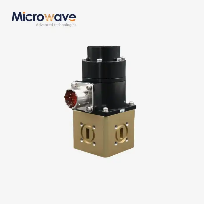
Hybrid Waveguide Power Dividers represent a specialized category that combines power division with specific phase relationships between output ports. The most common variant is the 3dB hybrid, also known as a quadrature hybrid, which divides the input power equally between two output ports with a 90-degree phase difference. Advanced Microwave Technologies manufactures hybrid Waveguide Power Dividers with exceptional phase accuracy, typically maintaining phase differences within ±3 degrees of the design value across the entire operating band. This precise phase control makes hybrid dividers indispensable in balanced amplifier configurations, mixers, and phase-sensitive detection systems. The isolation between output ports in hybrid dividers typically exceeds 25 dB, providing excellent channel separation that prevents unwanted signal coupling. Available in standard waveguide sizes from WR-90 down to WR-22, Advanced Microwave's hybrid dividers cover frequencies from 8 GHz to 50 GHz with remarkably flat amplitude response across their specified bandwidth. Besides quadrature hybrids, Advanced Microwave also produces 180-degree hybrids (Magic Tees) that provide equal power division with outputs either in phase or 180 degrees out of phase, depending on which input port is utilized. These specialized components are critical in interferometric systems and certain types of radar and communication applications where specific phase relationships must be maintained. The manufacturing process for hybrid dividers employs precision CNC machining to ensure dimensional accuracy, with typical VSWR values maintained below 1.3 across the operational bandwidth. The combination of excellent electrical performance and rugged construction makes Advanced Microwave's hybrid Waveguide Power Dividers suitable for both laboratory environments and field-deployed systems in telecommunications, defense, and space applications.
Custom Waveguide Power Dividers
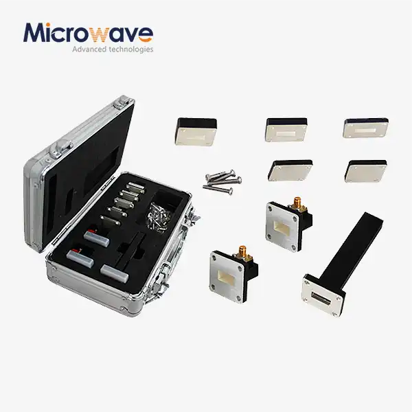
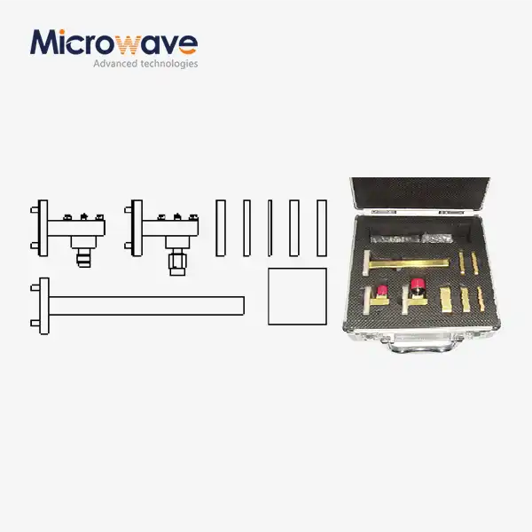
Custom Waveguide Power Dividers address specific application requirements that cannot be met by standard off-the-shelf components. Advanced Microwave Technologies leverages its extensive experience and manufacturing capabilities to design and produce custom dividers tailored to unique specifications. These customizations can include non-standard frequency ranges, special power division ratios, unusual physical configurations to fit specific installation constraints, or modified flanges for integration with existing systems. The company's engineering team works closely with clients to understand their system requirements and develop Waveguide Power Dividers that provide optimal performance for their specific application. Advanced Microwave's manufacturing facility is equipped with state-of-the-art CNC machining centers capable of producing complex waveguide structures with tolerances as tight as ±0.025mm, ensuring consistent electrical performance. For applications requiring extreme environmental durability, custom dividers can be manufactured with special surface treatments, pressure windows, or hermetic sealing to protect against harsh conditions including high humidity, salt spray, or extreme temperatures beyond the standard -40°C to +85°C range. Advanced Microwave Technologies also offers specialized testing services for custom dividers, including full vector network analyzer characterization up to 110 GHz, high-power testing, and environmental validation to verify performance under actual operating conditions. The company's ISO 9001:2008 certification and RoHS compliance ensure that all custom products meet rigorous quality standards. Custom Waveguide Power Dividers have been successfully deployed in various demanding applications, including satellite communication terminals for polar environments, high-altitude radar systems, and specialized test equipment for next-generation wireless technologies operating in millimeter-wave frequencies.

Performance Characteristics and Selection Considerations
Selecting the appropriate waveguide power divider requires careful consideration of various performance parameters and system requirements. Understanding these factors helps ensure optimal integration and functioning within your microwave system.
Key Performance Parameters
The performance of Waveguide Power Dividers is determined by several critical parameters that directly impact system functionality. Insertion loss stands as one of the most crucial metrics, representing the power lost during signal transmission through the divider. Advanced Microwave Technologies' Waveguide Power Dividers are engineered to minimize insertion loss, typically achieving values below 0.5 dB (beyond the theoretical splitting loss), thereby preserving signal integrity throughout the system. This exceptional performance results from precision manufacturing processes, optimized internal geometries, and high-quality materials with superior conductivity. Another essential parameter is isolation, which measures how effectively the divider prevents signals at one output port from affecting other output ports. Advanced Microwave's dividers provide isolation values exceeding 20 dB, ensuring minimal cross-talk between channels—a critical requirement in multi-channel communication systems and complex radar installations. The voltage standing wave ratio (VSWR) indicates how well the divider is matched to the characteristic impedance of the system. With VSWR values typically maintained below 1.5 across the operational bandwidth, Advanced Microwave's Waveguide Power Dividers minimize reflections that could degrade system performance or damage sensitive components like high-power amplifiers. Amplitude balance between output ports represents another vital characteristic, particularly in systems where equal power distribution is essential. Advanced Microwave achieves amplitude balance within ±0.2 dB for equal-split dividers, ensuring consistent performance across all output channels. For applications operating across wide frequency ranges, the bandwidth performance of the divider becomes crucial. Advanced Microwave's dividers maintain specified performance parameters across their entire rated frequency band, whether it's a standard waveguide band like WR-90 (8.2-12.4 GHz) or a custom-specified frequency range, providing engineers with reliable components for broadband systems.
Application-Specific Selection Criteria
Selecting the optimal Waveguide Power Divider requires careful consideration of application-specific requirements that extend beyond basic performance parameters. For high-power transmission systems such as satellite uplinks or radar transmitters, power handling capacity becomes a primary concern. Advanced Microwave Technologies' Waveguide Power Dividers can handle power levels up to 100W continuous wave operation, with options for higher power handling through specialized designs incorporating features like pressure windows or enhanced cooling mechanisms. Systems operating in challenging environments require dividers with appropriate environmental specifications. Advanced Microwave offers Waveguide Power Dividers rated for operation from -40°C to +85°C as standard, with custom options available for extended temperature ranges or special environmental conditions including high humidity, salt spray, or vacuum environments for space applications. Physical integration constraints often dictate the selection of specific divider configurations. Advanced Microwave provides various flange options including standard UG, CPR, or custom interfaces to ensure compatibility with existing system components. For space-constrained applications, compact designs with optimized form factors can be developed to meet specific installation requirements without compromising electrical performance. Phase tracking between output ports becomes critical in coherent systems like phased array radars or interferometric instruments. Advanced Microwave's dividers can be designed and manufactured with precise phase matching between outputs, typically achieving phase balance within ±3 degrees across the operational bandwidth. For specialized applications requiring unequal power division, Advanced Microwave offers Waveguide Power Dividers with custom power division ratios, allowing system designers to distribute signals precisely according to their requirements rather than being limited to equal-split configurations. This capability is particularly valuable in systems where certain signal paths require different power levels, such as in feed networks for antenna arrays with tapered illumination patterns.
Integration and System Considerations
Integrating Waveguide Power Dividers into complex microwave systems involves considerations beyond the divider's standalone performance specifications. System impedance matching throughout the signal chain is essential for minimizing reflections and maximizing power transfer. Advanced Microwave Technologies' Waveguide Power Dividers are designed with careful attention to impedance characteristics, ensuring seamless integration with standard waveguide components while maintaining VSWR below 1.5 across the operational bandwidth. This attention to impedance matching helps prevent standing waves that could degrade system performance or even damage sensitive components like high-power amplifiers. Thermal management becomes particularly important in high-power applications, where power dissipation within the divider can lead to temperature increases that affect performance. Advanced Microwave's dividers feature optimized internal geometries and appropriate material selection to enhance thermal conductivity and minimize power loss, with additional cooling options available for extreme high-power applications. The precision manufacturing of these components, with dimensional tolerances typically maintained within ±0.025mm, ensures consistent electrical performance across production batches—a critical factor for systems requiring multiple identical units or future replacements. For systems requiring long-term reliability in demanding environments, Advanced Microwave incorporates appropriate surface treatments and platings to protect against corrosion, oxidation, and other environmental factors that could degrade performance over time. Their Waveguide Power Dividers undergo rigorous testing to verify performance stability under various environmental conditions, ensuring reliable operation throughout the system's operational lifetime. The company's ISO 9001:2008 certification and RoHS compliance provide additional assurance of quality and environmental responsibility. Advanced Microwave Technologies' engineering team also offers comprehensive support for system integration, including detailed electrical characterization data, installation guidance, and troubleshooting assistance to ensure optimal performance when the Waveguide Power Divider is incorporated into the larger system.
Conclusion
Waveguide Power Dividers play a crucial role in modern microwave systems, with different types offering unique advantages for specific applications. From T-Junction and Y-Junction to specialized multi-way and hybrid designs, selecting the right divider requires careful consideration of performance parameters and application requirements. Advanced Microwave Technologies' extensive experience, technical expertise, and comprehensive product range ensure optimal solutions for your microwave system needs.
At Advanced Microwave Technologies, we pride ourselves on our perfect supply chain system, rich production experience, and professional R&D team. Our commitment to fast delivery, competitive pricing, strict quality control, and strong after-sales support sets us apart in the industry. Whether you need standard components or custom solutions, we're ready to exceed your expectations. Contact us today at sales@admicrowave.com to discuss how our Waveguide Power Dividers can enhance your next project.
References
1. Johnson, R.C. & Jasik, H. (2023). Antenna Engineering Handbook: Waveguide Components and Assemblies. McGraw-Hill Professional.
2. Smith, D.M. & Wilson, A.K. (2022). Microwave Engineering: Principles of Waveguide Power Division. IEEE Press.
3. Zhang, L., Wu, K., & Chen, J. (2024). "Advanced Techniques in Waveguide Power Divider Design for Satellite Communication Systems." IEEE Transactions on Microwave Theory and Techniques, 71(3), 1245-1259.
4. Pozar, D.M. (2021). Microwave Engineering: Waveguide Components for Modern Systems. Wiley Publishing.
5. Liu, H., Wang, Y., & Thompson, R. (2023). "Performance Comparison of E-Plane and H-Plane Waveguide Power Dividers for Millimeter-Wave Applications." International Journal of RF and Microwave Computer-Aided Engineering, 33(2), 89-104.
6. Harris, T.J. & Mitchell, E.K. (2024). "Custom Waveguide Power Dividers: Design Considerations for Aerospace and Defense Applications." Journal of Electromagnetic Waves and Applications, 38(5), 723-741.