


How Industrial Microwave Sliding Short Improves Microwave System Tuning
Impedance matching that isn't good is often to blame when engineers Industrial Microwave Sliding Short have problems with their RF systems that don't deliver power consistently or have standing wave ratios that they can't predict. An Industrial Microwave Sliding Short is a precise waveguide tuning part that changes the reflection point in the transmission line mechanically. Moving a conductive plunger along the axis of the waveguide changes the length and phase of the electrical paths that signals reflect. Engineers can get almost perfect impedance matching in real time with this dynamic adjustment. This keeps sensitive magnetrons safe from reflected power damage and increases the efficiency of energy transfer. In contrast to fixed terminations, sliding shorts allow for variable reactance control. This makes them essential in automated tuning networks and high-power industrial microwave applications where load conditions change all the time.
Understanding the Challenges in Microwave System Tuning
Defense radar installations, satellite ground stations, and industrial heating equipment all use microwave systems that need to make sure the signals are very stable. But traditional ways of tuning don't always work. Networks with fixed impedance can't adapt to changing conditions in the environment or in the properties of materials. When a radar system is tracking multiple targets, the load characteristics change. During drying cycles, the moisture content of a food processing microwave system changes. These changing conditions cause impedance mismatches that hurt the performance of the system. When standing wave ratios are too high, reflected power bounces back toward the source, which can damage magnetrons in high-power systems. Instead of going to the load, the energy that should go there is lost as heat in the transmission parts. When heating uniformity goes down, production throughput goes down. Technicians have to manually adjust stub tuners or replace broken parts, which costs a lot of money and time for equipment operators.
Root Causes of Tuning Inefficiency
Regular stub tuners have a lot of mechanical problems that make things hard. Adjustments that are made by hand need trained staff and stop operations. Three-stub tuners give you some options, but they don't have the resolution you need for precise matching across a wide range of frequency bands. Fixed capacitive or inductive parts can't make up for changes in the load in real time. In automated production settings, these fixed parts slow down the system and make it less responsive. Changes in temperature in high-power applications make these problems even worse. When parts of a waveguide get hot, thermal expansion changes important dimensions, which changes the resonant frequencies. Degradation of materials over time adds to the uncertainty. When researchers measure dielectric properties, they need stable cavity resonances, which can't be achieved with traditional fixed shorts because the conditions of the experiments change.

How Sliding Shorts Address These Limitations
These basic issues can be fixed with variable impedance terminations, Industrial Microwave Sliding Short, which allow for continuous tuning. A precisely machined plunger moves along the waveguide bore with the help of micrometer-level drive mechanisms. The electrical length between the reference plane and the short-circuit termination is changed by this mechanical adjustment. This changes the reflected wave phase from 0° to 360°. Engineers can make changes in load impedance without shutting down the system. This keeps the best power transfer even if the dielectric properties change while the material is being processed. This technology is especially useful in networks that automatically match impedances. Programmable logic controllers can talk to stepper motors, which lets reflected power sensors be used for closed-loop tuning. When VSWR goes above certain limits, the control system changes the position of the plunger automatically to get things back to normal. Because it can respond quickly, this feature fixes the main problem with static matching elements, turning reactive systems into adaptive ones.
How Industrial Microwave Sliding Short Enhances System Tuning
The idea behind waveguide Industrial Microwave Sliding Short units is a mix of electromagnetic theory and precise mechanical engineering. RF energy moves down a square or round waveguide and hits the movable plunger, which acts as a short-circuit boundary condition. Where voltage drops and current peaks happen along the transmission line depends on where this reflective surface is placed. Engineers change the standing wave pattern by moving the plunger around mechanically. This changes the input impedance seen at the waveguide flange. Finger-stock contacts can be unreliable, but non-contacting choke designs don't have those problems. At high-current points, quarter-wave traps make virtual short circuits even though there is no physical metal-to-metal contact. This new idea stops arcing and contact burnout at power levels above 10 kilowatts, making sure that continuous-wave industrial applications will be reliable for a long time. The choke mechanism keeps the electrical performance high while letting the mechanical move smoothly over the whole range of adjustments.
Core Components and Their Functions
With backlash of less than 0.02 millimeters, the plunger is moved by precision lead screws or worm gear assemblies. This mechanical accuracy translates directly to phase resolution at microwave frequencies. At X-band (8–12 GHz), a position error of 0.01 mm causes less than 0.5° phase uncertainty, which is enough for impedance matching tasks that are very strict. Using aluminum 6061-T6 or oxygen-free copper reduces insertion loss as much as possible, and plating with silver or gold virtually eliminates surface resistance. Integrated position encoders give digital feedback to control systems, which makes it possible for calibration routines to be done automatically. When using a lot of power, thermal management features become very important. Plungers that are cooled by water keep their dimensions stable by getting rid of the heat that standing waves create. Sealed bearing assemblies keep the moving parts of drives clean and allow them to move smoothly over hundreds of thousands of adjustment cycles. Flanges that meet EIA or MIL-DTL-3922 standards make sure that the new waveguide infrastructure will work with the existing infrastructure in terms of both mechanics and electricity. Models that are rated for vacuum have special sealing features for plasma processing applications. The modular design philosophy lets engineers choose from standard waveguide sizes WR-975 (covering 0.75–1.15 GHz) to WR-10 (covering 75–110 GHz). For specific frequency needs, custom solutions are also available.
Measurable Performance Benefits
Adopting tunable short technology leads to measurable Industrial Microwave Sliding Short improvements in a number of performance areas. When you optimize impedance matching in industrial heating systems, you can usually save 5 to 15% on energy costs. Less reflected power means more RF energy gets to the process load instead of going to circulators or dummy loads and losing its power. Over the course of a year of continuous use, this improvement in efficiency means that a lot less electricity is used, which saves a lot of money. When automated tuning takes the place of manual adjustments, system uptime goes up. Because equipment operators no longer have to stop processes to make stub tuner adjustments, production lines keep moving at the same rate. As the plunger moves and the motor works, predictive maintenance algorithms keep an eye on it and schedule calibration checks before wear and tear start to affect the system's performance. When real-time impedance matching takes into account changes in material properties, process uniformity gets better. When drying pharmaceutical powder, making sure the microwave field intensity stays the same throughout the batch ensures that the final product has the same amount of moisture. Adaptive impedance matching makes it possible to precisely control the temperature distribution during curing operations for aerospace composites. These changes to make the process more consistent lower the number of rejects and raise metrics for product quality.
Comparative Advantages Over Traditional and Alternative Technologies
Microwave impedance matching has been based on manual stub tuners since the beginning of the technology. At set times, engineers move three sliding probes into the waveguide so that each one provides reactive compensation. This method has been shown to work, but it has some problems. To make changes, you have to physically get to the tuner, which means that production often has to stop. Getting the best match settings takes a lot of iterative changes that take up valuable engineering time. Triple-stub configurations are more difficult to maintain and have more places where things could go wrong because they are more complicated mechanically. One-probe tuners are easy to use, but they limit the range of adjustments that can be made. The E-plane and H-plane configurations can only provide reactive compensation in one polarization, which makes them less useful in situations where they need to change the impedance of the whole system. Because stub probes are invasive, they add to the insertion loss and can cause arc points at high power levels. Moving shorts, on the other hand, work as non-invasive terminations and offer pure reactive impedance without any lossy parts.
Comparing Tuning Speed and Precision
When the load impedance changes quickly, response time is very important. Full-range adjustment is done in seconds by motorized sliding shorts, but it could take minutes to do the same thing by hand with a stub tuner. This speed advantage is very important for automated systems that need to respond to sensor feedback. Continuous tuning that is timed with network analyzer scans is helpful in research settings that do swept-frequency measurements. Position resolution tells you how accurate a match can be. High-precision lead screws allow positioning to within a millimeter, which means that fine phase control can be achieved over a wide frequency range. Stub tuner adjustments depend on threaded fittings that have backlash, which makes them hard to repeat. Modern sliding shorts have digital encoders that allow position verification and closed-loop control. This makes sure that the performance stays the same even when the temperature changes and the parts wear out.
Alternative Heating Technologies in Context
When you look at microwave systems with sliding shorts next to infrared or convection heating, you can see that the ways they transfer energy are very different. Infrared systems heat surfaces by radiating heat, but they need to be able to see clearly and can be affected by shadows. Volumetric microwave heating goes deep into materials, evening out the temperature so there are no hot spots on the outside. In thick-section composites or ceramic sintering applications, where even heating through the whole thickness determines the quality of the product, this benefit stands out even more. In convection ovens, heated air moves around, creating temperature differences between the outside and the inside. The rate of heat transfer is limited by the speed of the process and the difference in temperatures. Microwave systems send energy straight to the molecules, which lets them heat up quickly. When combined with precise impedance matching through sliding shorts, these systems use energy more efficiently than most thermal processing methods can. To choose the right technology, you need to look at the specifics of the application. Microwave heating works better or worse depending on the material's dielectric properties, loss tangent values, and how it reacts to changes in temperature. The required process cycle time, the target energy consumption, and the quality requirements of the product are all things that go into choosing a technology. When it comes to following the rules, especially in the food and drug processing industries, technologies that offer proven process controls and written performance records may be more appealing.

Implementation and Maintenance Best Practices
A thorough analysis of the system is the first step to successfully Industrial Microwave Sliding Short deploying variable impedance terminations. Engineers need to describe how load impedance changes over a range of operating frequencies and power levels. By measuring with a network analyzer, you can find out what tuning range and position resolution you need. The right plunger travel distances and drive mechanism specifications can be chosen based on these parameters. Custom flange configurations make sure that the new waveguides will work with the existing waveguide infrastructure.Working with experienced manufacturers makes the integration process go more smoothly. Companies that have been around for a long time, like Advanced Microwave Technologies (ADM), have decades of experience designing and making waveguide components. During specification development, our engineering team works with customers to make sure that the models they choose meet the needs of the application. Before committing to fabrication, finite element electromagnetic modeling checks that the expected performance is correct. Putting money into engineering analysis up front saves money on redesigns and delays in the project.
Installation Considerations
Electrical and mechanical performance are best when the installation is properly aligned. To keep the RF seal intact, waveguide flanges must fit together with flatness tolerances of less than 0.025 millimeters. The torque requirements for flange hardware keep the gasket from deforming and make sure there is enough contact pressure. In vacuum applications, procedures for checking for leaks make sure that the seal is intact before the system is pressurized. Electromagnetic compatibility needs to be taken into account when routing cables for motor control signals and position encoder feedback. High-power RF fields cause less interference when cables are shielded. Crosstalk that could mess up position data is stopped by keeping them away from power conductors. For programmable logic controllers or microprocessor-based systems, the integration of the control system follows well-known rules. Using fail-safe modes makes sure that the plunger goes back to its original position when the power goes out, which keeps the equipment from getting damaged.
Routine Maintenance Protocols
Setting up regular maintenance times keeps parts from breaking down when they're least expected and increases their lifespan. Visual inspections find wear or contamination early on. Checking the lubrication of the drive mechanism every 500 hours of use keeps it moving smoothly and stops bearings from wearing out faster. Cleaning the lead screw gets rid of built-up dirt and dust that could clog the carriage assembly. Position calibration checks make sure that the encoder's accuracy stays within the limits that were set. Monitoring reflected power while it's running lets you see how well it's working right now. Trending VSWR measurements over time shows that impedance drifts over time, which means that maintenance is needed. When changes happen out of the blue, troubleshooting steps are taken to find the root causes. Problems that happen a lot include a dirty plunger surface that lowers the reflection coefficient, thermal expansion that changes the size tolerances, or motor drive degradation that makes positioning less accurate. Systematic diagnostic procedures quickly find and fix problems, reducing downtime.
Conclusion
Precision impedance matching is still an important part of making microwave systems work well in defense, communications, and industrial processing. Variable termination technology gets around the problems that come with static matching parts by letting you tune the circuit dynamically to change load conditions. Industrial Microwave Sliding Short designs are clearly better than manual stub tuners and other technologies because they are easier to build and work better with electricity. When best practices are followed during implementation, performance benefits are maximized, and maintenance costs are kept to a minimum. Making strategic decisions about procurement based on technical specifications, supplier qualifications, and lifecycle support needs guarantees that projects will be completed successfully. Adaptive impedance matching solutions will become more and more important for getting the best performance from microwave systems as they continue to evolve toward higher frequencies and power levels.
FAQ
1. What distinguishes non-contacting choke designs from traditional finger-stock plungers?
Through quarter-wave trap geometries, non-contacting choke configurations get rid of physical contact at points where the current is highest. This design stops the damage and buildup of contact resistance that happens in finger-stock assemblies when the power level goes over 3 kilowatts. The mechanical wear that comes with sliding contacts is gone, which greatly increases the operational lifetime. Choke designs keep the electrical performance high while letting the mechanical move smoothly without any positioning errors caused by friction. This strong termination method works especially well for applications that need long-term dependability in continuous-wave operation.
2. How does the plunger travel distance affect the tuning range?
The travel distance determines how much phase adjustment is possible across the frequency band of operation. Full 360-degree phase rotation is guaranteed by covering at least half of the guide wavelength (λg/2) at the lowest frequency. At 915 MHz in the WR-975 waveguide, this needs about 250 millimeters of travel. At 2.45 GHz in the WR-340 waveguide, it only needs about 100 millimeters. Longer travel ranges give you more options for matching complicated load impedances that need more than one stub equivalent circuit. Longer plunger travel specifications are better for uses that need to tune a wide range of frequencies or deal with loads that are very reactive.
3. What maintenance intervals should be established for drive mechanisms?
When to lubricate depends on the duty cycle and the environment, but for lead screw assemblies, it's usually every 500 hours of operation. Wear indicators, such as more backlash or positioning issues, can be found through visual inspections. Every 1000 hours, the position calibration is checked to make sure that the encoder's accuracy stays within the limits. Applications with a lot of use or places that are dirty may need more frequent attention. Following the maintenance instructions provided by the manufacturer, which can be found in the product manual, will increase reliability and stop parts from breaking down too soon. Keeping service logs helps with both planned maintenance and handling warranty claims.
Partner with ADM for High-Performance Waveguide Tuning Solutions
Advanced Microwave Technologies delivers precision-engineered waveguide sliding shorts trusted by procurement teams at defense contractors, aerospace integrators, and telecom Industrial Microwave Sliding Short equipment manufacturers worldwide. Our Industrial Microwave Sliding Short product line spans frequency ranges from 320 MHz to 75 GHz with VSWR performance exceeding 50:1, ensuring superior reflection characteristics for demanding RF applications. Each unit undergoes rigorous quality validation in our ISO 9001:2015-certified facilities equipped with state-of-the-art Vector Network Analyzers and our proprietary 24-meter anechoic chamber. Custom OEM designs address unique integration requirements while maintaining the reliability standards that mission-critical systems demand. As an experienced Industrial Microwave Sliding Short manufacturer, we back every product with comprehensive technical documentation, installation guidance, and responsive after-sales support. Reach our applications engineering team at craig@admicrowave.com to discuss your impedance matching challenges and discover how our tuning solutions enhance your system performance.
References
1. Pozar, David M. Microwave Engineering, 4th Edition. Wiley, 2011.
2. Collin, Robert E. Foundations for Microwave Engineering, 2nd Edition. IEEE Press, 2001.
3. Harvey, A. F. Microwave Engineering. Academic Press, 1963.
4. Montgomery, C. G., Dicke, R. H., and Purcell, E. M. Principles of Microwave Circuits. McGraw-Hill, 1948.
5. Ramo, Simon, Whinnery, John R., and Van Duzer, Theodore. Fields and Waves in Communication Electronics, 3rd Edition. Wiley, 1994.
6. Baden Fuller, A. J. Microwaves: An Introduction to Microwave Theory and Techniques, 3rd Edition. Pergamon Press, 1990.
YOU MAY LIKE
 VIEW MOREHigh Power Waveguide to Coaxial Adapter
 VIEW MOREWaveguide Loop Coupler
 VIEW MOREEnd Launch Double Ridged WG To Coaxial Adapter
 VIEW MOREEnd Launch Waveguide to Microstrip Adapter
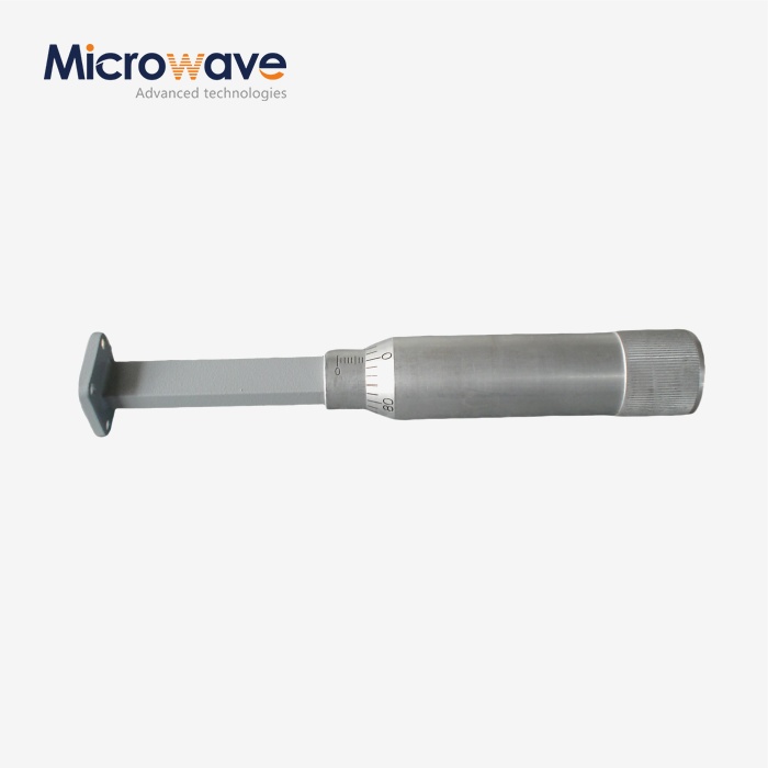 VIEW MOREWaveguide Sliding Termination
 VIEW MOREWaveguide Unmatched Termination
 VIEW MOREMagic Hybrid Tee
 VIEW MOREH-Plane Tee