





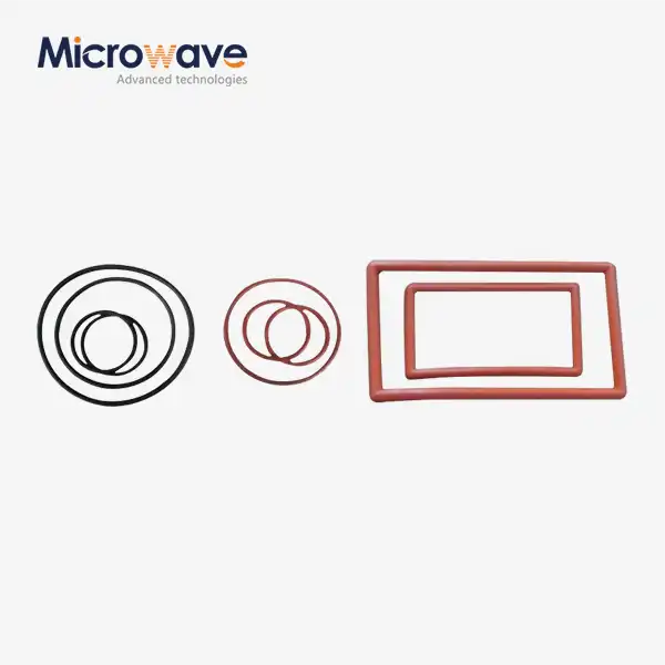
Waveguide Flange Gasket
Waveguide Flange Gasket for Standard Waveguide Sealing Flanges – D-Type & O-Type
The Advanced Microwave Technologies Co., Ltd. (ADM) company makes waveguide flange gaskets for standard waveguide sealing flanges that are either D-type or O-type. These gaskets fix two technical issues that happen in put-together waveguide systems: RF leakage at flange joints, which increases VSWR and insertion loss; and not enough sealing in pressurised runs that are exposed to wet, corrosive, or solvent atmospheres. The frequency range that ADM can produce and test goes from 0.5 GHz to 110 GHz, which covers all common waveguide uses.
What Is a Waveguide Flange Gasket and Why Does It Matter?
An item is an elastomer interface part that conducts electricity and is put between two flange surfaces that fit together. There are two things it does at once: it keeps the low-resistance electrical continuity across the joint to stop RF leakage and it creates a seal that keeps air and wetness out.
It's possible for RF to leak through tiny gaps between flanges, which can raise VSWR and add to the system's insertion loss. In waveguide runs that are pressurized—usually with dry nitrogen or dry air to stop voltage arcing—the gasket is also the main defence against dielectric breakdown and internal corrosion.
D-Type and O-Type: Two Standard Configurations
ADM's sealing rings are available in two standard configurations:
· D-Type Gasket: Matches the profile of cover-flange (UG-type) waveguide interfaces. The D-shaped cross-section provides consistent compression across the sealing surface and helps maintain alignment during assembly.
· O-Type Gasket: Designed for choke-flange connections. The circular cross-section seats within a machined groove, maintaining consistent contact pressure and resisting extrusion under applied bolt torque.
The correct type depends on your flange standard — cover versus choke — and the bolt torque specifications for the assembly. Both configurations are available for common waveguide sizes including WR-90, WR-137, and other standard series.
Material Composition
The electrical and environmental performance of a waveguide flange gasket depends on its material system. ADM's gaskets use a two-component structure combining a polymer binder with conductive filler particles.
Binder options:
· Silicone — general-purpose use, wide operating temperature range
· Fluorosilicone — for environments with exposure to jet fuels, hydraulic fluids, solvents, or oils, where standard silicone would swell and lose sealing integrity
Conductive filler options:
· Silver-plated Aluminum (Ag/Al) — preferred for aluminum flanges; reduces galvanic corrosion risk in salt-fog and humid outdoor environments
· Silver-plated Copper (Ag/Cu) — higher bulk conductivity for RF-demanding assemblies
· Nickel-Graphite (Ni/C) — cost-effective option for installations where corrosion exposure is low
Selecting the right binder and filler combination for your flange material and operating environment is the most important material decision in the specification process.

Key Technical Parameters
Parameter | Value / Specification |
Frequency Range | 1 GHz to 100+ GHz |
Volume Resistivity | < 0.005 ohm-cm |
Shielding Effectiveness | > 100 dB (10 MHz – 10 GHz) |
Temperature Range (Fluorosilicone) | −55°C to +125°C |
Standard Thickness | 0.027" or 0.032" |
Dimensional Tolerance | ±0.005 inches |
Compatible Waveguide Sizes | WR-90, WR-137, and other standard sizes |
Material Standard | MIL-DTL-83528 |
Types Available | D-Type, O-Type |
Application Scenarios
Aerospace Radar in the Air
During the entire -55°C to +125°C working range, airborne radar assemblies are subject to high vibration and fast temperature changes. When the radar system is under dynamic load, fluorosilicone-based gaskets keep the seals intact and the electricity flowing. They also don't break down when they come into contact with jet fuel or hydraulic fluid, so the VSWR stays within the required range.
SATCOM Stations on the Ground
In satellite uplinks, high-power amplifier waveguide runs need gaskets that keep pressurised areas sealed and keep the current flow consistent and low-resistance. If the flange joints in these assemblies aren't sealed properly, they can become hotspots with high power densities or let water in, which damages the pressurised dry-gas environment.
Arrays for Marine and Naval Communications
Galvanic corrosion can happen when different metals touch each other and are exposed to salt spray. When used in marine environments, silver-aluminum filled silicone gaskets are a suitable choice for aluminum-flange antenna arrays because the Ag/Al filler system is designed to reduce the electrochemical potential difference at the gasket-to-flange interface.
Quality Control and Inspection
Each batch of sealing parts that ADM makes goes through a detailed inspection process.
Verification of Dimensions: Optical measurement shows that the internal aperture dimensions stay within 0.005 inches. Any gasket material that gets into the waveguide aperture creates an iris effect that sends signals backward.
Astm D991 Volume Resistivity Testing: Electrical conductivity is checked against targets on the data sheet. Less than 0.005 ohm-cm is achieved by high-performance grades; the acceptable range depends on the type of filler used.
Shielding Effectiveness Testing (IEEE-STD-299 / MIL-DTL-83528): Material attenuation of plane-wave fields is confirmed by batch testing, with passing scores above 100 dB.
Visual Inspection: Every gasket is looked at to see if there are any foreign object debris (FOD), holes in the elastomer matrix, or uneven filler particle distribution that might cause RF hotspots or mechanical weak spots.
Installation and Handling
The goal for the gasket's compression deflection during fitting is 10 to 15% of its original thickness. When you over-torque, you can crush conductive filler particles or push material into the waveguide aperture. When you under-torque, the EMI seal isn't complete, and sealed systems may lose pressure.
Standard thicknesses of 0.027" and 0.032" are big enough to fit most flange surface flaws without changing the length of the electrical path in a way that would change the impedance.
Do not reuse a waveguide flange gasket. Once they are initially torqued, conductive elastomers take on a permanent compression set. A used gasket doesn't always block electromagnetic waves (EMI) and doesn't always close properly under pressure. The seal needs to be changed every time the flange joint is opened.
FAQ
Q: If I open the flange for repair, can I use the gasket again?
A: Not really. After the first twisting, the elastomer forever changes shape. It changes both the EMI shielding and the pressure sealing when it is used again. If you open a flange joint again, you should always put on a new gasket.
Q: How do I pick between fluorosilicone and silicone?
A: You can use rubber for many different things. If the installation will be exposed to jet fuels, hydraulic fluids, solvents, or oils, choose fluorosilicone instead of standard silicone, which will swell and lose its shape in these situations.
Q: What makes galvanic corrosion happen at flange joints, and how can I stop it?
A: Galvanic corrosion happens when two different metals touch each other and an electrolyte, like water, acts as a bridge. For aluminium flanges, the conductive filler should be Ag/Al or Ni/C. This will lower the electrochemical potential that is driving the reaction.
Q: Does the width of the gasket change how well the RF works?
A: Yes. While thicker seals smooth out rough surfaces, they also lengthen the electrical path, which can slightly change the impedance. The standard thicknesses of 0.027" and 0.032" are a proven balance between electrical performance and surface compensation.
Q: What kind of gasket material should be used on aluminium flanges that are installed outside?
A: Silver-aluminum (Ag/Al) filled rubber is the most common choice. When put together against aluminium plates outside in salt fog or high humidity, this filler system is designed to reduce galvanic corrosion as much as possible.
Contact Us
To request a quote or discuss a custom size or material specification for Waveguide Flange Gasket, contact ADM at craig@admicrowave.com.
YOU MAY LIKE
 VIEW MOREEnd Launch Waveguide to Coaxial Adapter
 VIEW MORERight Angle Waveguide to Microstrip Adapter
 VIEW MOREPlastic Flange Caps
 VIEW MOREWaveguide Adjustable Support
 VIEW MOREActive Limiter
 VIEW MOREFeed Fired Lens Antenna
 VIEW MORELadder Membrane Square Dual Circular Polarization Horn Antenna
 VIEW MOREAntenna Near Field Measurement Probe