





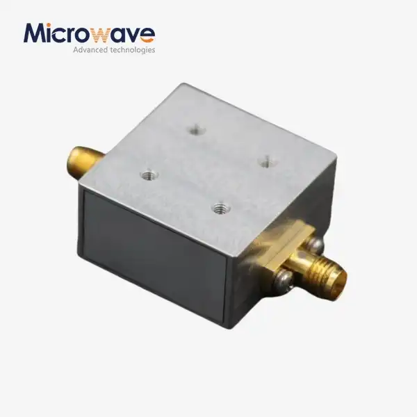
cpw waveguide
Low Loss
Good Impedance Control
Planar Structure, Easy Integration
Good Heat Dissipation
CPW Waveguide Planar Transmission Line Solutions for High-Frequency RF and Microwave Applications
Advanced Microwave Technologies Co., Ltd. (ADM) designs and manufactures cpw waveguide products for precision signal transmission in demanding microwave environments. A coplanar waveguide consists of a center signal conductor between two co-planar ground planes on a single dielectric substrate surface, separated by tiny gaps. ADM’s test infrastructure ranges from 0.5 GHz to 110 GHz, and the product line is designed for MMIC, 5G/6G, aerospace and quantum computing applications that demand both impedance precision and low loss.
What Is a CPW Waveguide and How Does It Work?
Uniplanar A product uses uniplanar design – the signal conductor and both ground planes lie on the same side of the dielectric substrate, unlike microstrip lines. This allows shunt components to be directly grounded, without via holes, eliminating a typical source of parasitic inductance.
The construction facilitates the propagation of quasi-TEM mode with low dispersion at millimeter-wave frequencies above 30 GHz. The impedance is regulated by the width of the gap (S) and the width of the conductors (W). The design is less susceptible to the fluctuations of the height of the substrate than the microstrip arrangements.
The effective dielectric constant is usually between 5.0 and 9.0 depending on the substrate material such as Alumina, GaAs or Rogers laminates.
Key Technical Features
ADM's coplanar waveguide products are built around four core performance characteristics:
· Low Loss: High-conductivity metallization (Gold or Copper) reduces skin-effect losses at high operating frequencies.
· Impedance Control: Standard 50Ω or 75Ω characteristic impedance is achieved through precise gap-to-width ratio management.
· Planar Structure for Easy Integration: The uniplanar design eliminates the need for via holes when grounding shunt components, avoiding parasitic inductance that would otherwise affect gain and bandwidth.
· Thermal Management Option: Conductor-Backed CPW (CBCPW) configurations add a bottom ground plane, improving mechanical strength and heat dissipation for high-power applications.
Technical Parameter Overview
Parameter | Specification / Range |
Characteristic Impedance | 50Ω or 75Ω (standard) |
Effective Dielectric Constant (εeff) | 5.0 – 9.0 (substrate dependent) |
Supported Substrates | Alumina, GaAs, Rogers Laminates |
Metallization | Gold (Au) or Copper (Cu) |
Surface Finish | ENIG or Immersion Silver (preferred) |
Frequency Range (ADM Testing) | 0.5 GHz – 110 GHz |
Gap Width Tolerance (QC) | ±5% (AOI verified) |
Impedance Verification Method | TDR (Time Domain Reflectometry) |
Quality Standards | IPC-6012, AS9100D |
Application Scenarios
Monolithic Microwave Integrated Circuits (MMICs): In aerospace and defense radar systems, cpw waveguide structures allow direct surface mounting of active components such as FETs and diodes. There is no need for grounding vias, which helps keep the gain and bandwidth performance.
5G/6G Electro-Optic Modulators: In the backhaul infrastructure of telecommunications systems, coplanar waveguide electrodes on Lithium Niobate modulators allow microwave signals and optical waves to match in speed, with bandwidths exceeding 100 GHz.
Superconducting Quantum Computing: Coplanar waveguide resonators are a common way to build qubits in cryogenic settings. Their flat shape cuts down on dielectric loss and lets high-Q resonators work on silicon or sapphire substrates, which is important for keeping the quantum state.
Quality Control Process
ADM uses quality control at every step of the production process to make sure that the signal quality stays the same.
Dimensional Tolerance Inspection: Automatic Optical Inspection (AOI) checks that changes in gap width stay within 5%. This keeps the gearbox line's impedance from becoming mismatched.
Metallisation and Surface Roughness: Profile measures show that the surface roughness stays below the skin depth at the desired frequency, which has a direct impact on the conductor loss.
Impedance Verification: Time Domain Reflectometry (TDR) tests show that the characteristic impedance is 50Ω along the whole length of the trace.
Integrity of the Air Bridge: A scanning electron microscope (SEM) checks air bridge structures for shorts or physical damage in ways that stop slotline modes.
Substrate Loss Tangent Verification: The IPC-TM-650 standards are used to check the dielectric material properties, such as the Dk and Df values, to make sure that all production batches work the same way.
Surface finishes like ENIG or Immersion Silver are used as usual. It is best to stay away from HASL because its uneven surface planarization can change gap capacitance and make high frequency impedance accuracy less accurate.
Design Considerations and Customization
The operating frequency, the type of substrate, and the impedance goal all affect the best way to set up a cpw waveguide. The engineers at ADM can help you make plans for all of these things that are just right for you.
When you stitch CBCPW designs together, you stop parallel-plate waveguide mode resonances that can hurt performance at higher frequencies.
That being said, you should also think about how close the top cover is to the body. ADM keeps a vertical keep-out distance that is at least 5 to 10 times the gap width. This way, when the enclosures are close to each other, the characteristic impedance doesn't change.
The 24-meter microwave anechoic chamber at ADM is used to test unique designs before they are sent out. It can measure both near-field and far-field antennas.
Why Choose ADM for Coplanar Waveguide Products?
ADM has been working in microwave engineering for more than 20 years and has its own research and development lab as well as offices in Xi'an, Chengdu, Beijing, Tianjin, and Shijiazhuang. It also has test equipment that can work at frequencies from 0.5 GHz to 110 GHz.
The products are made to meet the norms of IPC-6012 and AS9100D. The engineering team gives technical advice and help with custom designs. Before an order is delivered, it goes through pre-shipment testing.
If you have specific needs for frequency, substrate, or impedance, the engineering team is where you should start. Contact information is given below.
FAQ
Q: What's the difference between a product and a microstrip line?
A: A product places ground planes on the same layer as the signal conductor. This one-plane design doesn't have any through holes for connecting shunt parts, which lowers parasitic inductance. For microstrip, the ground path needs a separate bottom ground plane and vias.
Q: What's the worst thing about the product when it comes to high frequencies?
A: If the right steps aren't taken during design, a coplanar waveguide can support an unwanted slotline mode that sends out radiation and loses signals. To make this less of a problem, bond wires or air bridges are used to make the ground potentials across the building equal.
Q: What is Conductor-Backed CPW (CBCPW) used for?
A: Adding a bottom ground plane makes CBCPW stronger and better at getting rid of heat, so it can be used in high-power situations. To stop parallel-plate waveguide mode resonances in this setup, via stitching is needed.
Q: Does the product care about how close the enclosure is?
A: Yes. If you put the top cover too close, it can change the characteristic impedance. In order to stop this from happening, a vertical keep-out distance of at least 5 to 10 times the gap width is kept during design.
Q: What is the best surface finish for making high-frequency coplanar waveguides?
A: It is best to use ENIG or Immersion Silver. People don't use HASL because its rough surface can change gap capacitance and make high frequency impedance accuracy worse.
Q: Does ADM handle custom substrate and impedance needs?
A: The answer is yes. ADM can work with Alumina, GaAs, and Rogers laminates, and the gap-to-width ratio can be changed to meet specific impedance goals over a wide frequency range.
Contact Us
Contact ADM's engineering team at craig@admicrowave.com to discuss your cpw waveguide requirements, request technical consultation, or get a project-specific quote.