






Waveguide Horn Antennas
Waveguide Horn Antennas – Standard Gain Series for Microwave & Millimeter-Wave Applications
Waveguide Horn Antennas with frequencies from 0.5 GHz to 110 GHz are designed and made by Advanced Microwave Technologies Co., Ltd. (ADM). These antennas are made of high-conductivity aluminium or copper and have gold, silver, or passivation finishes on the outside. They come with standard gain options of 10 dBi, 15 dBi, 20 dBi, and 25 dBi. You can ask for custom gain values, aperture sizes, and waveguide band configurations. All of the units are checked with a Vector Network Analyser that has been adjusted and by measuring the far-field radiation pattern in ADM's 24-meter Microwave Darkroom.
What Are Waveguide Horn Antennas?
A horn antenna is a type of aperture antenna that moves electromagnetic energy from a hollow metal waveguide into space. The slowly expanding structure changes the impedance between the waveguide and the 377-ohm impedance of empty space. This keeps signal reflection low over the whole operating range.
In frequencies above 1 GHz, coaxial feeds cause more insertion loss and can cause dielectric arcing at high power levels. Both problems can be solved by horn antennas. They are made of all metal and don't have any resonant elements, so they can handle high peak power without breaking. Also, the shape of the aperture makes the gain predictable, with a normal VSWR of less than 1.5:1 (tightened to less than 1.2:1 in precision models).
Because the gain can be predicted, horn antennas are often used as a standard for calibrating RF measurement tools in rooms with no sound.
Key Technical Properties
Three physical factors mainly affect how well an antenna called a horn works electrically. These are the flaring angle, the aperture dimensions, and the waveguide band. Together, these things determine the frequency range that can be used and the highest gain that can be reached at any point in that range.
Choice of material has a direct effect on how well gearbox works. Copper or aluminium with high conductivity is used for the main body, and gold or silver plating lowers ohmic losses and protects the surface from oxidation over a long service life. Passivation is a cheaper option for places that don't need as much strength.
The antenna works across the whole waveguide band because it doesn't have any resonant parts. The side-lobe levels stay low, and the radiation pattern is clear and can be repeated. During ADM's production verification process, simulation models are used to check the gain, beamwidth, and side-lobe performance.


Product Specifications
Parameter | Details |
Antenna Type | Standard Gain Horn Antenna |
Polarization | Linear |
Standard Gain Options | 10 dBi, 15 dBi, 20 dBi, 25 dBi |
Typical Operating Example | WR-90 (X-band, 8.2–12.4 GHz) |
VSWR | < 1.5:1 standard; < 1.2:1 precision models |
Material | Aluminum / Copper |
Surface Finish | Gold plating / Silver plating / Passivation |
Flange Interface | UG-387 (and other standard flanges) |
Frequency Testing Range | 0.5 GHz – 110 GHz |
Customization | Gain values, horn dimensions, frequency band |
Note: Gain increases toward the upper end of the operating band because the fixed physical aperture becomes electrically larger as wavelength decreases. This behavior is predictable and should be accounted for in your system link budget.
Application Scenarios
EMC/EMI Testing and Setting Up of Antennas
As standard antennas in anechoic chambers for testing wireless devices, 5G base station gear, and car radar sensors, waveguide horn antennas with known theoretical gain values are used. Because the aperture gain can be calculated, the field strength can be found without having to do a separate gain calibration step.
Ground Stations for Satellite Communication
In ground sites that are connected to the earth, horn antennas feed parabolic reflector dishes. The aperture illumination pattern is meant to balance the efficiency of the reflector against the loss of light due to spillover. The geometry is chosen based on the dish f/D ratio and the edge taper that is needed.
High-Power Radar Systems
Horn antennas can handle high peak power levels without breaking because they are made of metal and don't have any insulating materials. This means they can be used in radar applications where power handling is one of the most important design constraints, along with gain and beamwidth.
Quality Control Process
Every ADM horn antenna goes through a structured verification process before shipment:
· VSWR / Return Loss — Measured with a calibrated VNA to confirm the impedance match is within specification across the full operating bandwidth.
· Radiation Pattern Verification — Far-field range testing confirms gain, half-power beamwidth (HPBW), and side-lobe levels against simulation models.
· Mechanical Tolerance Check — Aperture dimensions and flange flatness are measured to prevent RF leakage at the UG-387 or equivalent interface.
· Surface Finish Inspection — Plating coverage (gold, silver, or passivation) is checked to confirm conductivity and corrosion resistance meet production standards.
ADM's 24-meter Microwave Darkroom supports both near-field and far-field measurement configurations, allowing the appropriate method to be selected based on antenna size and frequency range.
Customization and Supply Options
Standard gain horn antennas cover the most common frequency and gain requirements, but system-level projects frequently need configurations outside the standard range. ADM's engineering team can work with you on:
· Gain values outside the 10–25 dBi standard range
· Modified aperture dimensions targeting a specific beamwidth
· Alternative waveguide band configurations
· Special plating or environmental sealing for outdoor or harsh-environment deployment
ADM maintains production and technical support operations across multiple locations in China to serve customers in different regions. For inquiries about Waveguide Horn Antennas, lead time, minimum order quantities, or specific technical requirements, contact the team directly.
FAQ
Q: How do I choose the best horn antenna for my needs?
A: First, figure out what frequency range you need. This will tell you what waveguide band to use, like WR-90 for X-band. Then, decide what gain you want, which tells you what aperture size and horn length to use. Once those two parameters are set, check your system budget against the VSWR limits and power handling needs.
Q: What determines the amount of power that can be handled?
A: The electric field breakdown level of the air inside the waveguide controls how much power can be used. When the peak power level is very high, the waveguide assembly might need to be pressurised. The horn design should avoid having any sharp internal edges or surface flaws that could lower the local breakdown threshold.
Q: Why does the gain change from one frequency band to the next?
A: The aperture's size stays the same, so as the frequency goes up, the gain goes up too because the aperture gets bigger electrically compared to the wavelength. It is possible to predict how the gain changes across a standard waveguide band, and the aperture dimensions can be used to figure it out if link budget planning is needed.
Q: Can these antennas be used in outdoor environments?
A: Standard horn antennas are open structures that don't have built-in weather protection. For use outside, a low-loss dielectric radome or opening cover is suggested, and weather-sealed flanges should be asked for to keep the interface seal.
Q: What is the difference between a conical horn antenna and a pyramidal horn antenna?
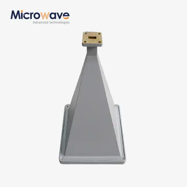
A: Pyramidal horns connect to rectangular waveguides and make output that is linearly polarised and has a rectangular aperture. If you change the feed network, the conical horns can support either linear or circular polarisation. They connect to circular waveguides. Which one to use depends on the type of waveguide and the polarisation needs.
Q: Can ADM provide the product with gain values that aren't standard?
A: Yes. ADM can take orders for boost levels above or below the normal 10–25 dBi range, and they can change the size, type, and finish of the horns to fit the needs of each system. Send the engineering team your frequency range and gain goal so they can look it over.
Contact Us
For quotes or technical questions about Waveguide Horn Antennas, contact our engineering team at craig@admicrowave.com.
YOU MAY LIKE
 VIEW MOREMMDS Transmitting Antenna
 VIEW MOREConical Horn Lens Antenna
 VIEW MOREPyramid Horn Lens Antenna
 VIEW MOREPoint Focusing Horn Lens Antenna
 VIEW MOREFeed Fired Lens Antenna
 VIEW MORECorrugated Horn and Multimode Horn Antenna
 VIEW MOREWideband Double-ridged Horn Antenna
 VIEW MOREMini Wideband Double-ridged Horn Antenna