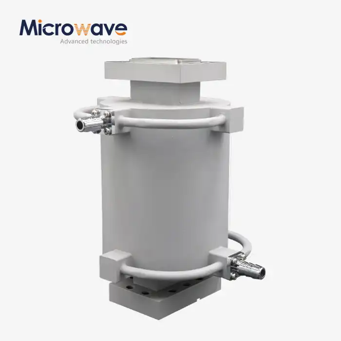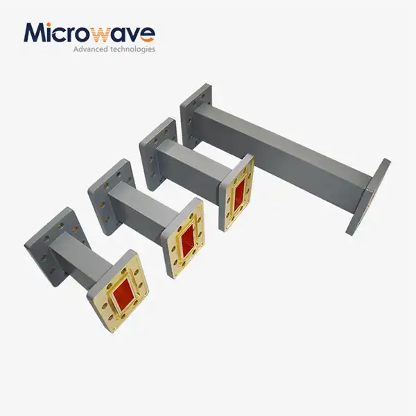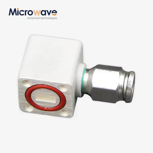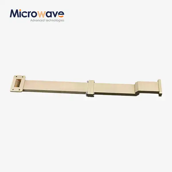






Coaxial Power Detector
Coaxial Power Detector for RF & Microwave Systems
The Coaxial Power Detector is made by Advanced Microwave Technologies Co., Ltd. (ADM) and is used in tough RF and microwave measurement settings. Each unit checks the average power, peak power, and pulse power in coaxial communication lines from 10 MHz to 40+ GHz (gigahertz). The Schottky diode architecture provides response times on the nanosecond level, and the ruggedised coaxial housing keeps performance stable in harsh field conditions. The impedance is set to 50 ohms, which keeps the VSWR below 1.35:1.
What Is a Coaxial Power Detector?
A product changes the RF power on a coaxial transmission line into a proportional DC voltage or digital output. It also keeps an eye on the signal amplitude all the time without getting in the way of the main signal path too much.
Schottky diode contacts inside each unit are set up for fast switching, which supports signal envelopes with a lot of frequencies. There are zero-bias designs that get rid of the need for external DC bias and make circuit integration easier.
Average power, peak/envelope power, and pulse power are the three main types of power that these devices measure. Because they have so many measurement modes, they can be used to both track continuous-wave transmitters and quickly profile radar pulses.

Key Technical Specifications
Parameter | Specification |
Frequency Range | 10 MHz – 40+ GHz (L, S, X, Ka-bands) |
Dynamic Range | –50 dBm to +20 dBm |
VSWR | ≤ 1.35:1 (typical) |
Impedance | 50 Ohms |
Response Time | Nanosecond-level rise time |
Frequency Flatness | ±0.5 dB across operational band |
Max Input Power | +20 to +23 dBm (diode limit) |
Operating Temperature | –55°C to +85°C |
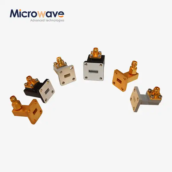
Connector Options | SMA, N-Type, 2.92mm |
Core Technical Features
Because it can work with frequencies from 10 MHz to 40+ GHz, a single coaxial power detector can be used in a number of different system setups, from L-band communication links to Ka-band satellite uplinks, without the need to change units.
The detector can pick up the first few pulses of radar and switch between transmitting and receiving (T/R) modules before the receiver front ends are hit by high-power returns thanks to its nanosecond-level reaction time.
Low insertion loss makes sure that the main signal path loses as little power as possible. The unit works as a nearly clear part while still giving a correct reading of the voltage across the working range.
The toughened coaxial housing blocks electromagnetic waves and cools the device, so it works well even in environments with a lot of vibration and temperature changes, like those found in outdoor and flying installations.
Quality Control Process
Before sending any unit out, ADM checks it through a structured quality control process.
A Vector Network Analyser (VNA) that has been calibrated is used to sweep the whole operating band for frequency response and flatness verification. To make sure that results are always the same across frequencies, the output voltage must change by no more than 0.5 dB.
Testing for input return loss and VSWR shows that signal reflection stays within the allowed range (usually VSWR < 1.35), which means that the detector doesn't affect the source's performance.
Transfer curve linearity testing checks the relationship between P_in and V_out against a power meter reference that has been calibrated. From these measurements for each unit, calibration look-up tables are made.
Thermal cycling and burn-in put each unit through a lot of quick temperature changes while it's plugged in. This finds early problems with semiconductors or solder joints before the product gets to the field.
Precision metrology is used for connector interface gauging to check the depth of the center conductor pin. This keeps system cables from getting damaged while they are mating.
Application Scenarios
5G Base Stations and DAS Networks
Power Amplifier (PA) output is watched by the detection in real time in MIMO antenna arrays. Feedback information is sent to pre-distortion circuits to make the PA behave more linearly and more efficiently, even in outdoor tower-mounted setups where amplifier temperatures change quickly.
Radar Systems for Space and Defence
When there is a lot of vibration, the detector works from –55°C to +85°C. It helps protect Low Noise Amplifiers (LNAs) from overpowering, profiles radar pulse envelopes, and supports T/R switching timing.
Automated Test Equipment (ATE) and Calibration Labs
The detector is built into test fixtures on RF component production lines. It allows for quick pass/fail testing of cable assemblies and transmitters, with an instant voltage-to-power readout that works well for high-volume manufacturing processes.
RF Device Manufacturing and R&D Labs
Engineers use the coaxial power detector for Automatic Gain Control (AGC) loop design, transmitter output verification, and fault diagnosis during product development and production quality checks.
Customization and Supply Options
ADM can be set up in a way that fits the needs of a specific system. You can choose a SMA, N-Type, or 2.92mm connector link. The frequency range, dynamic range, and housing formats can be changed so that they can be used in embedded systems or as test fixtures on a bench.
There are ADM branches in Xi'an, Chengdu, Beijing, Tianjin, and Shijiazhuang, and all of them have engineering support. The 24-meter Microwave Darkroom, which covers frequencies from 0.5 GHz to 110 GHz, and the in-house R&D lab are used to test unique designs before they are sent to production.
FAQ
Q: What's the difference between a peak/envelope detector and an RMS detector?
A: An RMS-responding detector finds out how much power a signal really has, which is important for complex modulated waveforms like QAM or OFDM. A peak/envelope detector uses diodes to find voltage peaks. This is faster and works well for pulse radar or AM modulation, but non-sinusoidal signals may need correction factors.
Q: How does the video bandwidth affect how well the detector works?
A: How quickly the output voltage can change in response to changes in the RF wave is given by the video bandwidth. For waves less than 1 µs, you need a detector with a large video bandwidth and a quick rise time. If the bandwidth is too low, the detector will average the pulse and give you the wrong peak reading.
Q: Does this device need a biasing voltage to work?
A: Yes, zero-bias Schottky detectors work without an external DC bias because they use the contact potential of the metal-semiconductor junction. This makes designing the circuit easier. Biased versions might be better at keeping their sensitivity and temperature stability at very low power levels.
Q: What happens if the power coming in is higher than the highest rating?
A: If you go over the diode breakdown voltage or heat dissipation limit, the detector will be broken forever. An attenuator should be put in line before the detector input if the signal path power goes above the working range, which is usually +20 to +23 dBm.
Q: How often does a product need to be calibrated?
A: Calibration intervals for embedded monitoring applications depend on the needs of the system. For testing and measuring, the volts-per-watt transfer function should be calibrated once a year to account for diode wear and connector ageing. This keeps the function accurate over time.
Q: What kind of connection should be used for Ka-band applications?
A: The 2.92mm (K connector) interface is best for Ka-band frequencies above 26.5 GHz. At millimeter-wave frequencies, where SMA connectors start to lose their effectiveness, it keeps its low reflection and consistent impedance matching.
Contact Us
Send your coaxial power detector project requirements or technical questions to craig@admicrowave.com.